
System for providing continuous electric power from solar energy

a solar energy and power system technology, applied in the field of hybrid solar power systems, can solve the problems of insufficient efficiency for certain applications, current concept designs of long endurance near space vehicles are limited by payload and propulsion capabilities, and the dependence of fuel on the power propulsion system and onboard components of the near space vehicl

Inactive Publication Date: 2008-03-06
HARRIS CORP
View PDF16 Cites 40 Cited by
  • Summary
  • Abstract
  • Description
  • Claims
  • Application Information

AI Technical Summary

Benefits of technology

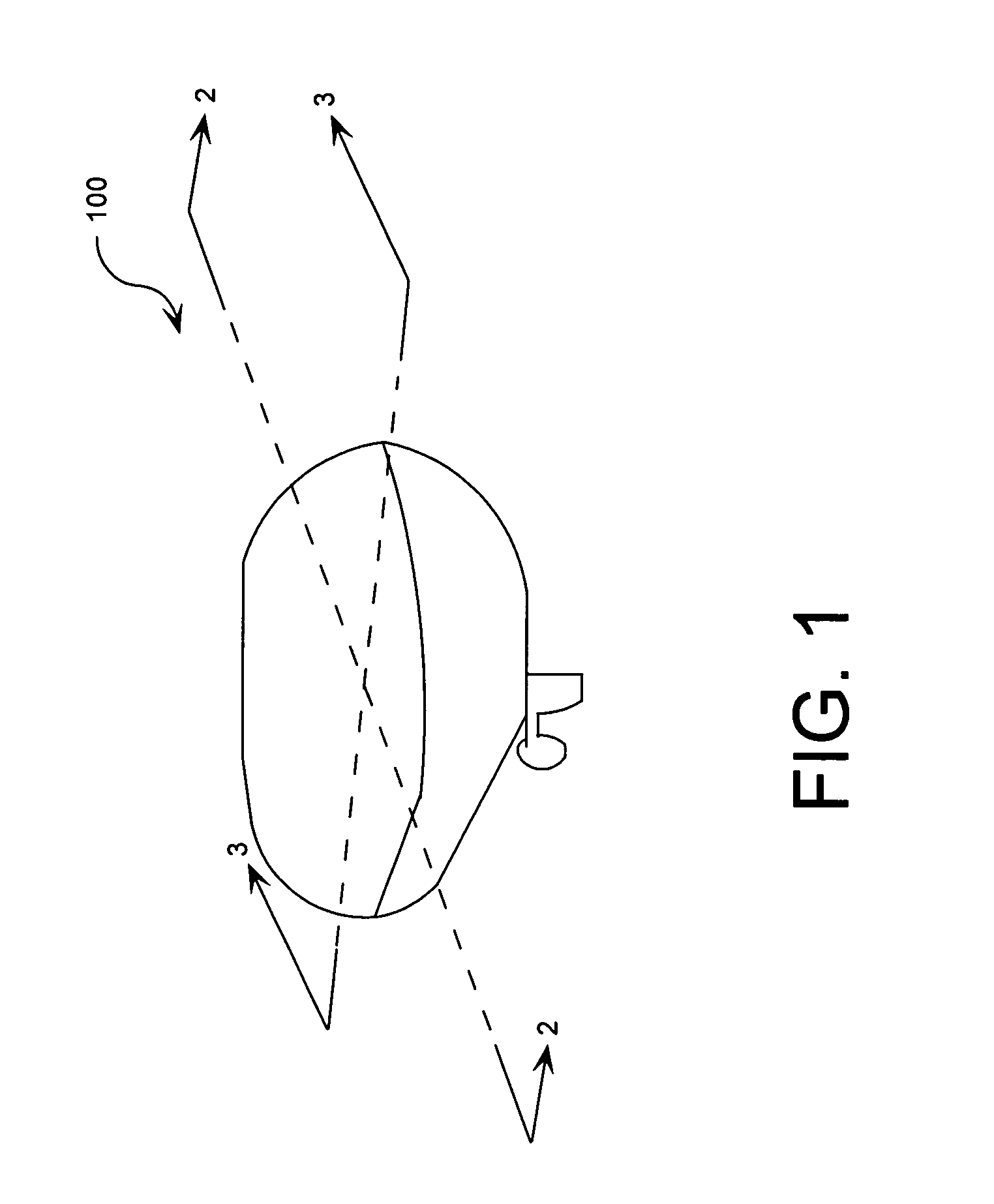
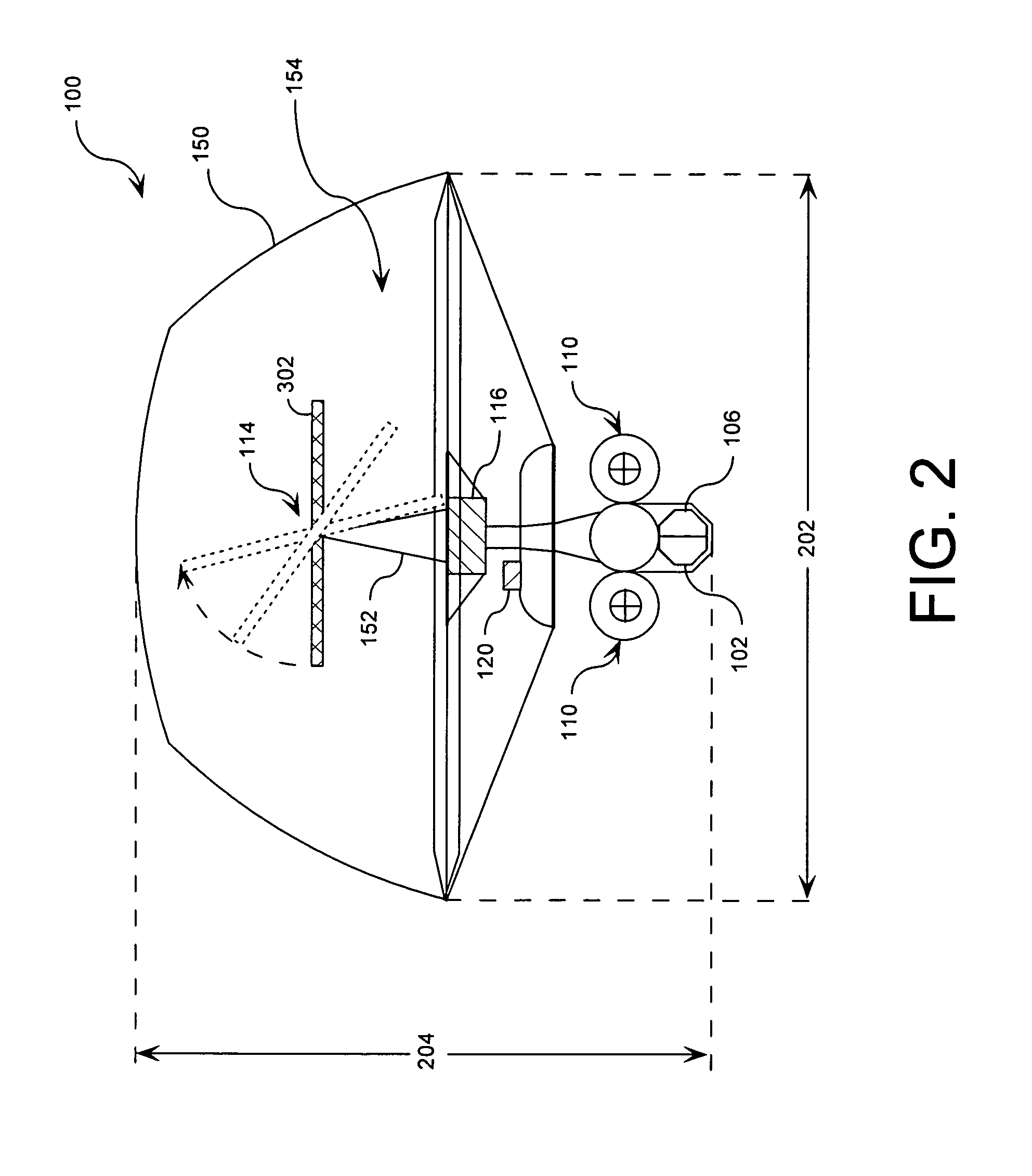
[0020]The method can also include positioning the vehicle at a near space altitude (e.g., 60,000 feet above sea level). When positioned in this way, a temperature differential between a working fluid and a surrounding atmosphere (e.g., −60° F.) at the near space altitude is used to power an engine disposed in the vehicle. The method also advantageously includes selectively controlling a position of the vehicle. The method can further include selectively controlling an orientation of the solar concentrator such that the solar concentrator is constantly facing a source of solar radiation. According to one aspect of the invention, a control system can control the position / orientation of the vehicle and the orientation of the solar concentrator onboard the vehicle so that the solar concentrator constantly faces a source of solar radiation.

Problems solved by technology

Despite the advantages offered by the foregoing systems, they still have not achieved a level of efficiency necessary for certain applications.
Current concept designs of long endurance near space vehicles are limited by their payload and propulsion capabilities.
One limitation comes from a near space vehicle's dependency on fuel to power propulsion systems and onboard components, such as radars, sensors, imaging devices, control systems, and radio transmitters.
A large amount of weight is invested to carrying a sufficient amount of fuel for flight.
Consequently, the overall capabilities of a near space vehicle are limited.
The current designs of battery powered near space vehicles are also limited by their endurance capabilities.

Method used


Image

  • System for providing continuous electric power from solar energy
  • System for providing continuous electric power from solar energy
  • System for providing continuous electric power from solar energy

Examples


Embodiment Construction

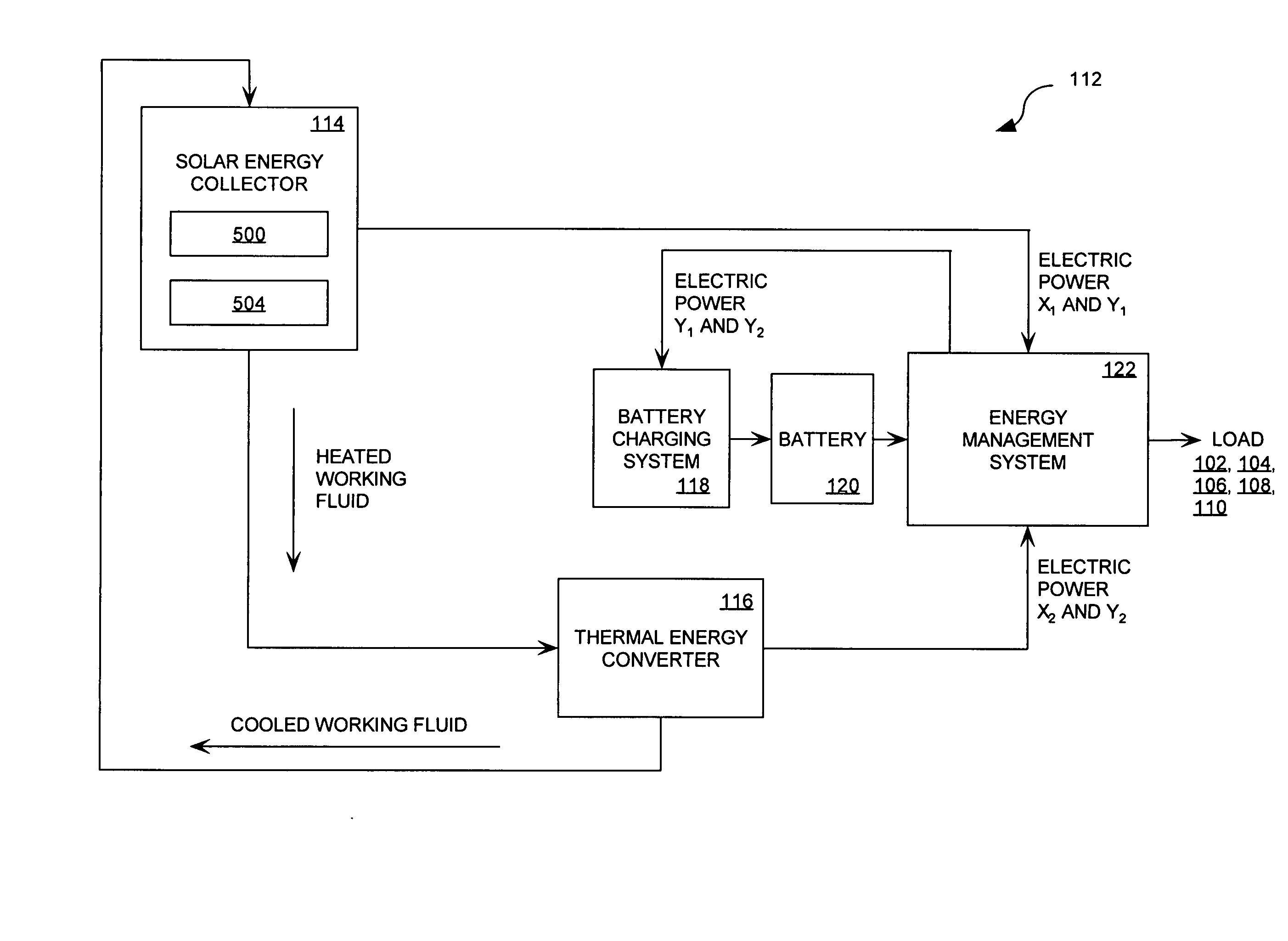
[0035]The invention concerns a system for generating electric power from solar energy. The system includes a solar energy collector that has a reflective surface. The reflective surface is a solar concentrator formed into a shaped surface for focusing solar radiation toward an elongated solar energy collection zone provided at a focal center (or along a focal line) defined by the reflective surface. An elongated PV / thermal device is positioned at the focal center (or along the focal line) within the solar energy collection zone. The PV / thermal device includes a photovoltaic array and a thermal energy collector. The photovoltaic array converts solar energy into electrical power. The thermal energy collector has fluid conduits to provide passageways for the flow of a working fluid. The working fluid collects thermal energy as it flows through the thermal energy collector. The working fluid is used by a thermal energy converter to convert the thermal energy to electric power. In this r...


PUM


Abstract

A system (112) for providing continuous electric power from solar energy is provided. The system includes a solar concentrator (302) formed of an optically reflective material having a curved surface that defines a focal center or a focal line toward which light incident on the curved surface is reflected. The system also includes a PV / thermal device (310) positioned substantially at the focal center or along the focal line. The PV / thermal device is comprised of a photovoltaic array (500) and a fluid cooling system for the photovoltaic array. The fluid cooling system includes a thermal energy collector (504). A battery charging system (118) is coupled to the photovoltaic array. The battery charging system includes a battery charging circuit. The battery charging system is programmed to selectively provide a charging current for the battery charging circuit during periods when the solar concentrator is exposed to solar radiation. The charging current can be selected so that a battery (120) charged by the battery charging circuit has power to continuously operate a load during periods when the solar concentrator is not exposed to solar radiation.

Description

BACKGROUND OF THE INVENTION[0001]1. Statement of the Technical Field[0002]The invention concerns power systems, and more particularly, hybrid solar power systems that can convert solar energy into electric power.[0003]2. Description of the Related Art[0004]There are currently in use a wide variety of systems and methods for utilizing solar power as a source of energy. For example, photovoltaic systems are widely known for converting sunlight into electricity. Another common type of system is the solar trough. The solar trough is a type of solar thermal system where sunlight is concentrated by a curved reflector onto a pipe containing a working fluid that can be used for process heat or to produce electricity. Solar thermal electric power plants using solar trough technology are well known.[0005]A variation of the solar trough technology is a photovoltaic concentrator system. The photovoltaic concentrator system uses sun-tracking mirrors that reflect light onto a receiver lined with ...

Claims


Application Information

Patent Timeline
Patent Type & Authority Applications(United States)
IPC IPC(8): H02N6/00
CPCF03G6/065F24J2/14Y02E10/46Y02E10/52H01L31/0547H02S99/00H02S40/44H01L31/0543Y02E10/60F24S23/74
Inventor PALMER, WILLIAM ROBERT
Owner HARRIS CORP
Learn More