Imaging reader with variable range

a technology of imaging reader and variable range, applied in the direction of electromagnetic radiation sensing, exposure control, instruments, etc., can solve problems such as accidental reading, and achieve the effects of reducing the working distance range, and increasing the working distance rang

Active Publication Date: 2008-03-06
SYMBOL TECH LLC
View PDF6 Cites 11 Cited by
  • Summary
  • Abstract
  • Description
  • Claims
  • Application Information

AI Technical Summary

Benefits of technology

[0008]A one- or two-dimensional, solid-state imager is mounted in the housing, and includes an array of image sensors operative for capturing light from a one- or two-dimensional symbol through the window over a field of view during the reading. Preferably, the array is a CCD or a CMOS array. The imager is preferably associated with a high-speed strobe illuminator to enable the image of the symbol to be acquired in a very short period of time, for example, on the order of 500 microseconds, so that the symbol image is not blurred even if there is relative motion between the imager and the symbol. The strobe illumination is preferably brighter than ambient illumination, especially close to the window.
[0009]In accordance with this invention, the range of working distances of the imaging reader is varied. For example, if the imaging reader is placed on a countertop in a restricted space, then the working distance range is advantageously reduced to prevent symbols on nearby items that are not to be transacted from being accidentally read. If the imaging reader is picked up from the countertop to read a symbol on a product that cannot be easily placed on the countertop, then the working distance range is advantageously increased to read the symbol on the remote product, and is advantageously decreased when the reader is returned to the countertop. If a stand is used, then a reduced working distance range is advantageously employed when the reader is mounted in the stand, and an increased working distance range is advantageously employed when the reader is held in the operator's hand.
[0010]The change in the working distance range can be accomplished automatically or manually. For example, if the stand is used, then controls can be employed on the reader and the stand in order to detect the presence or absence of the reader in the stand and to vary the working distance range accordingly. Such controls may include a magnet and an associated magnetic sensor such as a reed switch or a Hall effect sensor. An optical sensor or a mechanical switch could also be used. The range can also be changed by sending a command from a host computer to the reader, or by scanning a special purpose symbol that reconfigures the reader.

Problems solved by technology

When such imaging readers are placed on a countertop in a restricted space, symbols on nearby items that are not to be transacted, but still within the range of working distances, might be accidentally read.
When such imaging readers are picked up to read a symbol on a product that cannot be easily placed on the countertop, a fixed range of working distances sufficient to read close-in symbols on the countertop might be insufficient to read far-out symbols located off the countertop.

Method used


Image

  • Imaging reader with variable range
  • Imaging reader with variable range
  • Imaging reader with variable range

Examples


Embodiment Construction

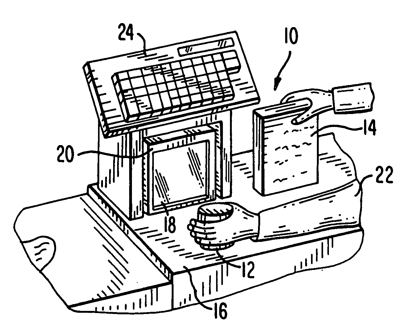
[0019]Reference numeral 10 in FIG. 1 generally identifies an electro-optical reader in a workstation mode for processing transactions and mounted on a checkout counter at a retail site at which products, such as a can 12 or a box 14, each bearing a target symbol, are processed for purchase. The counter includes a countertop 16 across which the products are slid at a swipe speed past a generally vertical window 18 of a box-shaped vertical slot reader 20 mounted on the countertop 16. A checkout clerk or operator 22 is located at one side of the countertop, and the reader 20 is located at the opposite side. A cash / credit register 24 is located within easy reach of the operator. The reader 20 is portable and lightweight and may be picked up from the countertop 16 by the operator 22, and the window 18 may be aimed at a symbol preferably on a product too heavy or too large to be easily positioned on the countertop in front of the reader in the workstation mode.

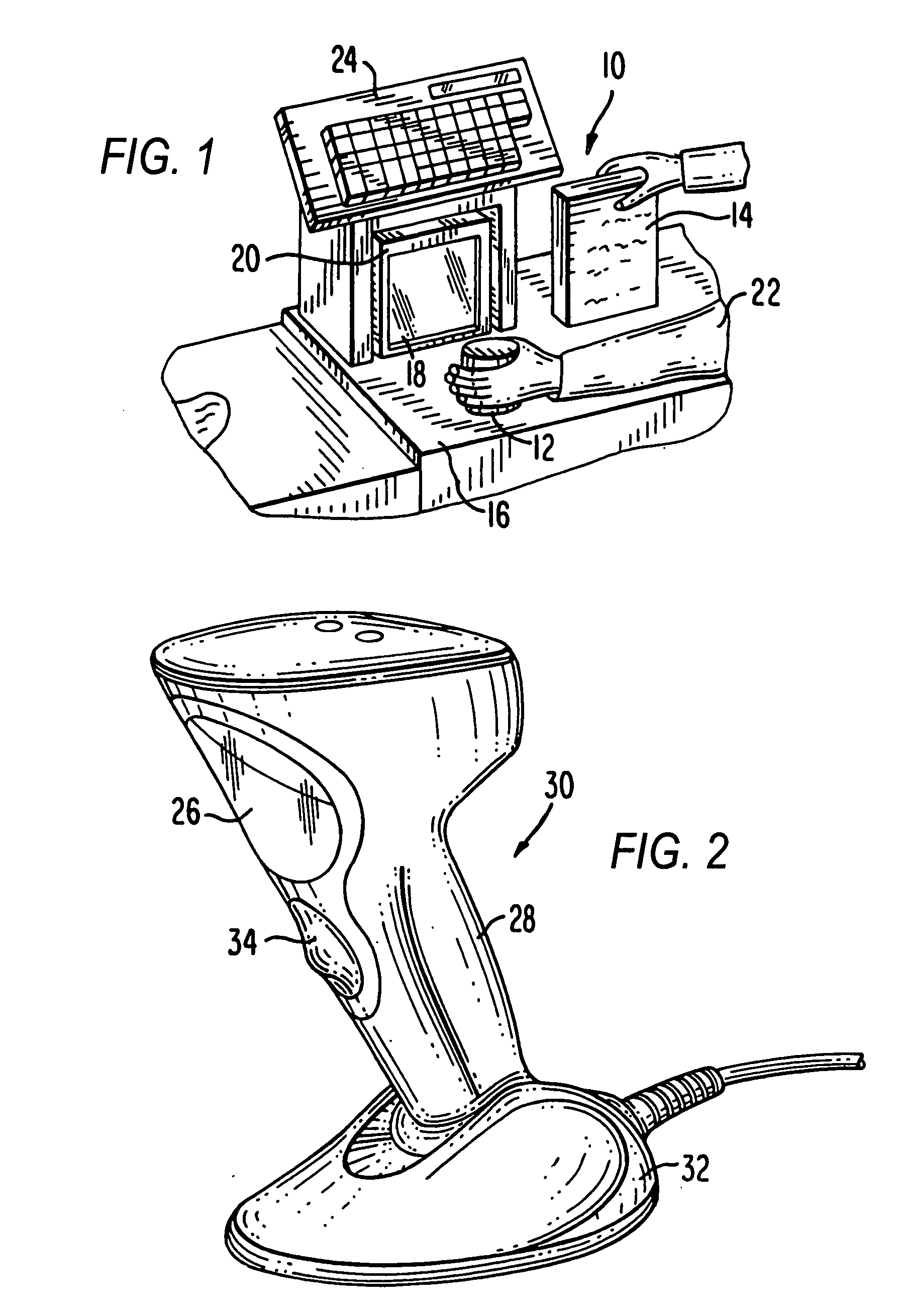
[0020]Reference numeral 30 i...


PUM


Abstract

A solid-state imager in a reader for electro-optically reading indicia located in a range of working distances includes an array of image sensors for capturing light from the indicia over a field of view during the reading. The range of working distances in which the indicia are read is varied, either automatically or manually.

Description

DESCRIPTION OF THE RELATED ART[0001]Flat bed laser readers, also known as horizontal slot scanners, have been used to electro-optically read one-dimensional bar code symbols, particularly of the Universal Product Code (UPC) type, at a point-of-transaction workstation in supermarkets, warehouse clubs, department stores, and other kinds of retailers for many years. As exemplified by U.S. Pat. No. 5,059,779; No. 5,124,539 and No. 5,200,599, a single, horizontal window is set flush with, and built into, a horizontal countertop of the workstation. Products to be purchased bear an identifying symbol and are typically slid or swiped across the horizontal window through which a multitude of scan lines is projected in a generally upwards direction. When at least one of the scan lines sweeps over a symbol associated with a product, the symbol is processed and read.[0002]The multitude of scan lines is generated by a scan pattern generator which includes a laser for emitting a laser beam at a m...

Claims


Application Information

Patent Timeline
Patent Type & Authority Applications(United States)
IPC IPC(8): G06K7/10
CPCG06K7/10811G06K7/10722
Inventor BARKAN, EDWARD
Owner SYMBOL TECH LLC
Why Eureka
Try Eureka