

Shelf-like display machine and image display method
- Summary
- Abstract
- Description
- Claims
- Application Information
AI Technical Summary
Benefits of technology
Problems solved by technology
Method used
Image

Examples
first embodiment
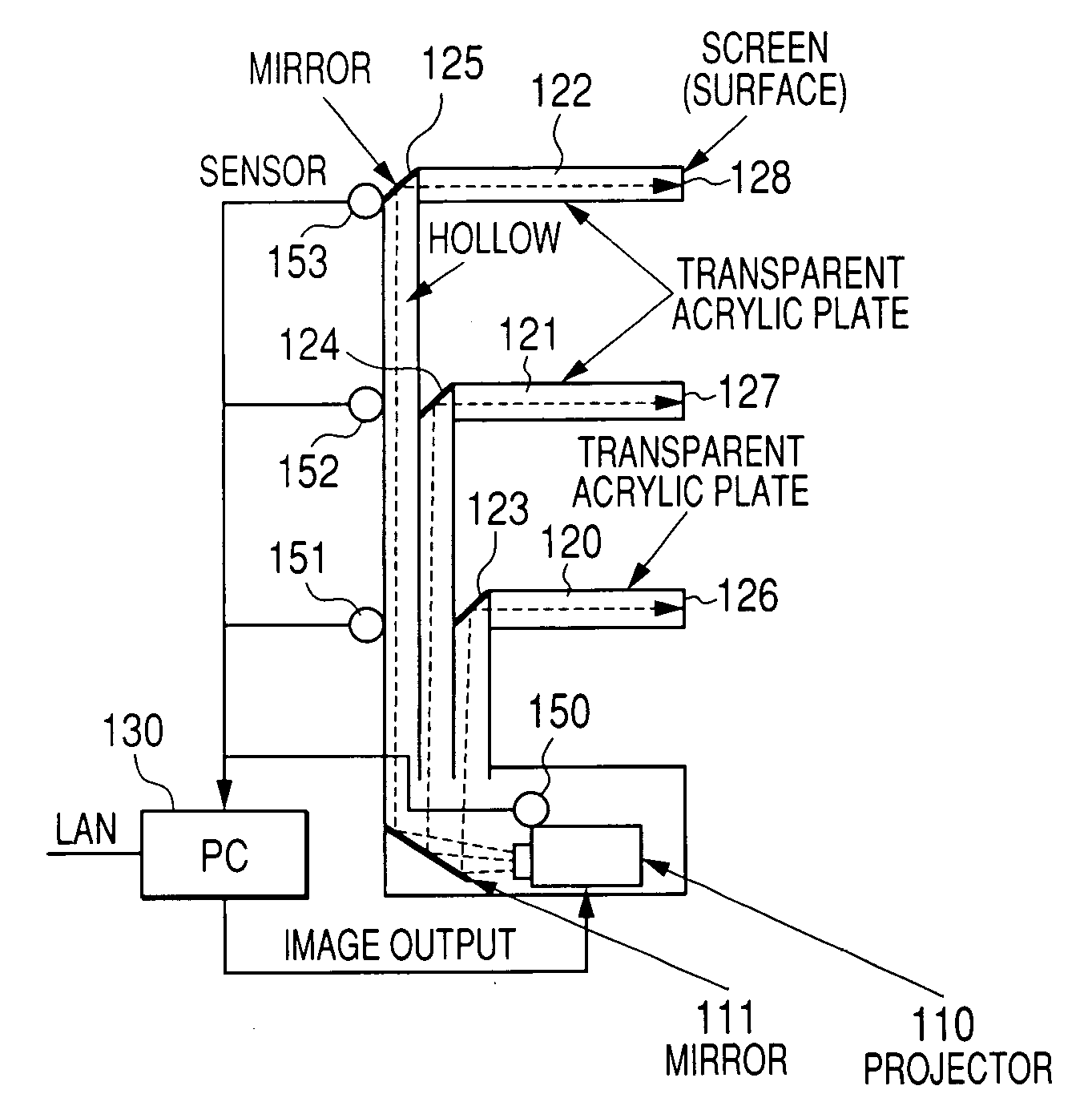
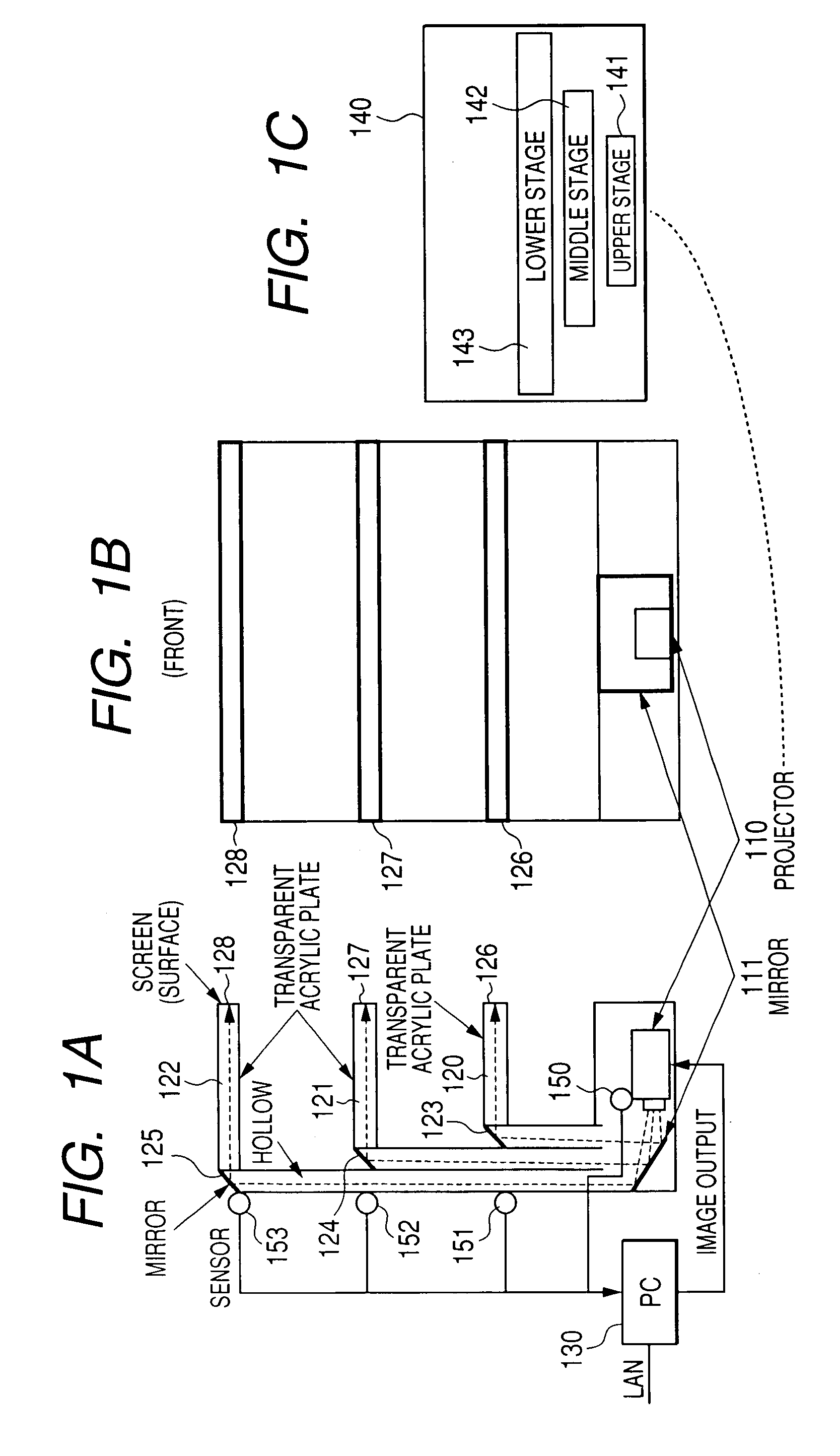
[0046]FIGS. 1A to 1C show a side elevational view and a front elevational view of shelves of one preferred embodiment and an example of display of images to be projected to a projector. As shown in the side elevational view of FIG. 1A and the front elevational view of FIG. 1B, light projected from the light source such as a projector 110 projecting an image is reflected upward through a reflector member such as a mirror 111, the light passes through the rear member constituted by a member with hollow state or characteristic allowing light to be passed through it, the light is reflected again with mirrors 123, 124, and 125 arranged at the backs of the shelves 120, 121, and 122 having light transparent characteristic (using cavity and member through which light is transmitted, for example) and then the light is projected to the ends 126, 127, and 128 of the shelves. Screen raw material for collecting light or dispersing light is applied to the ends of the shelves to enable either lett...
second embodiment
[0060]Next, there will be described a method for projecting an image to a place other than the end of the shelf-like member. At first, referring to FIG. 13, there will be described a method for projecting an image to the upper surface of a shelf. FIG. 13 shows a side elevational view and a front elevational view of a shelf. The image projected by the projector 110 is reflected upward by a mirror 111, passes through a shelf 670 of transparent raw material, is reflected downward by a mirror 671 mounted at the lower portion of the shelf and the image is projected to a screen 672 arranged at the upper portion of the shelf. Projection of the image onto the upper surface of the shelf through this method enables an image to be projected to goods placed on the shelf or the image to be displayed around the goods.
[0061]Next, referring to FIG. 14, there will be described a method for projecting an image to the screen arranged at a shelf in a vertical orientation. The image projected by the pro...
third embodiment
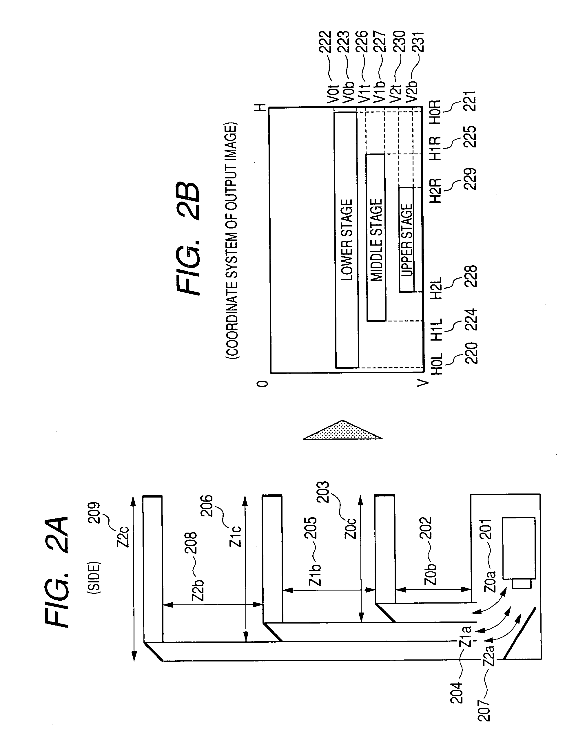
[0063]Since optical path lengths from the projector to each of the screens are different from each other, the methods described above up to now correct the image projected from the projector so as to correct a difference in magnifying powers caused by the difference in optical path length and perform an output display. In turn, setting the optical path lengths ranging from the projector to each of the screens substantially equal to each other in this preferred embodiment eliminates an image correcting processing. In addition, the preferred embodiment has an effect that the focal point is strictly set for every image because the optical path lengths ranging from the projector to each of the screens are substantially set equal to each other. This situation will be described in detail as follows.
[0064]Referring now to FIG. 16, there will be described a method for changing a depth of a shelf. Image projected from the projector 110 is projected to screens 701, 702 and 703 at the ends of ...
PUM
 Abstract
Description
Claims
Application Information