Telemetry system and method with variable parameters

a telemetry system and variable parameter technology, applied in the field of telemetry systems, can solve the problems of limited data transmission and reception range of implantable devices, limited freedom of movement of implantable devices, and inability to move freely, so as to increase the bandwidth of programmable circuits

Active Publication Date: 2008-03-06
MEDTRONIC MIMIMED INC
View PDF9 Cites 45 Cited by
  • Summary
  • Abstract
  • Description
  • Claims
  • Application Information

AI Technical Summary

Benefits of technology

[0013] The programmable circuit may further include a second coil having a first node and a second node; a switch having a first node and a second node; and a resistive element having a first node and a second node. The second coil may be inductively coupled to the first coil. The first node of the switch may be connected to the first node of the second coil. The first node of the resistive element may be connected to the second node of the switch. The second node of the resistive element may be connected to the second node of the second coil. Closing the switch may increase a bandwidth of the programmable circuit. The second coil may be an inductor. The resistive element may be a resistor or a semiconductor.
[0019] The telemetry circuit may further include a second coil having a first node and a second node; a switch having a first node and a second node; and a resistive element having a first node and a second node. The second coil may be inductively coupled to the first coil, the first node of the switch may be connected to the first node of the second coil, the first node of the resistive element may be connected to the second node of the switch, and the second node of the resistive element may be connected to the second node of the second coil. Closing the switch may increase a bandwidth of the programmable circuit.
[0020] According to an embodiment of the present invention, a method for modifying circuit parameters of a telemetry circuit may include providing a first coil for transmitting an input signal, the first coil having a first node and a second node; providing a high impedance path having a first node and a second node; providing a low impedance path having a first node and a second node, the low impedance path connected in parallel with the high impedance path; providing a capacitive path having a first node and a second node; the first node of the capacitive path connected to a second node of the first coil; providing an input path for coupling signals into the high impedance path, the low impedance path, and the capacitive path; connecting the first node of the first coil to the first node of the high impedance path and the first node of the low impedance path; connecting the first node of the capacitive path to the second node of the first coil; connecting the capacitive path to the high impedance path and the low impedance path such that the capacitive path forms a circuitous path with the high impedance path and the low impedance path; and enabling either the high impedance path or the low impedance path.
[0022] The method may further include providing a second coil having a first node and a second node; providing a switch having a first node and a second node; providing a resistive element having a first node and a second node; inductively coupling the second coil to the first coil; connecting the first node of the switch to the first node of the second coil; connecting the first node of the resistive element to the second node of the switch and the second node of the resistive element to the second node of the second coil; and closing the switch to increase a bandwidth of the telemetry circuit.
[0027] The implantable communication device may also include a second coil having a first node and a second node, the second coil being inductively coupled to the first coil; a switch having a first node and a second node, the first node of the switch being connected to the first node of the second coil; and a resistive element having a first node and a second node, the first node of the resistive element being connected to the second node of the switch, the second node of the resistive element being connected to the second node of the second coil. Closing the switch may increase a bandwidth of the programmable circuit. The second coil may be an inductor. The resistive element may be a resistor or a semiconductor.

Problems solved by technology

The use of implantable devices to remedy medical conditions is becoming increasingly frequent as the size and cost of such devices shrink.
For example, in the past, many diabetics who have needed blood glucose analysis on a daily basis or even multiple times during a day and who have required insulin injections in response to the analysis have been limited in their freedom of movement due to the requirement of remaining close to the analysis and treatment equipment.
For example, because the data transmission and reception range of the implantable device is necessarily limited, primarily due to power limitations and safety concerns having to due with data transmission from within a human body, the person with the implantable device must remain in relatively close proximity to the controller, within inches, in some circumstances.
Moreover, because data transmission rates of implantable devices are limited, also due to power limitations, the transmission of large amounts of data can take an exceedingly long time.
The transmission and reception of data, software or other information encompassing tens of kbytes to hundreds of kbytes and more can impose inconvenient restrictions on the freedom of the person with the implantable device, restrictions that the implantable device was supposed to remedy.
Alternatively, in the past, telemetry circuit designers have compromised and have tried to find a balance between data transmission rate and data transmission range, maximizing neither.

Method used


Image

  • Telemetry system and method with variable parameters
  • Telemetry system and method with variable parameters
  • Telemetry system and method with variable parameters

Examples


Embodiment Construction

[0036] In the following description of preferred embodiments, reference is made to the accompanying drawings which form a part hereof, and in which are shown by way of illustration specific embodiments in which the invention may be practiced. It is to be understood that other embodiments may be utilized and structural changes may be made without departing from the scope of the preferred embodiments of the present invention.

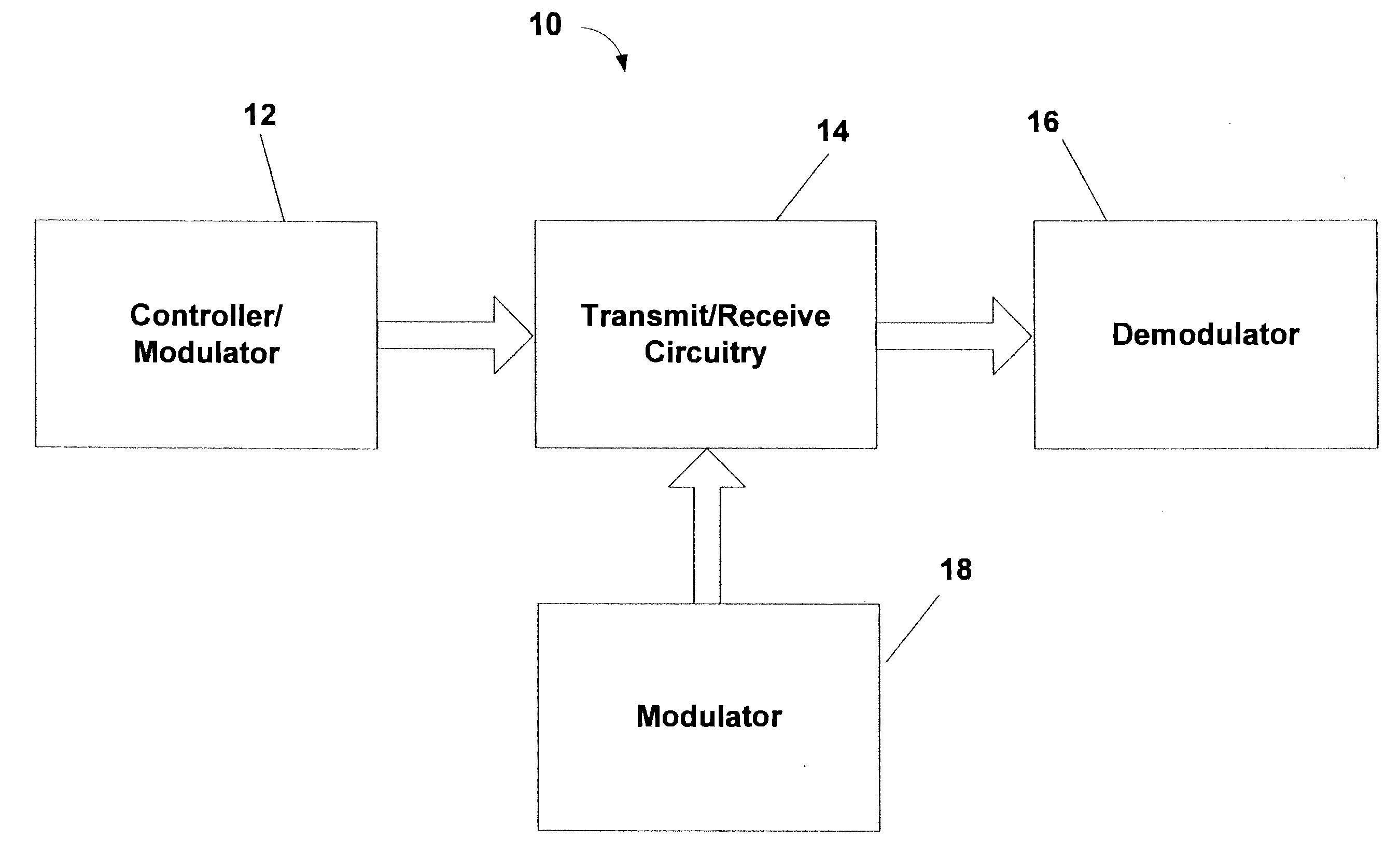
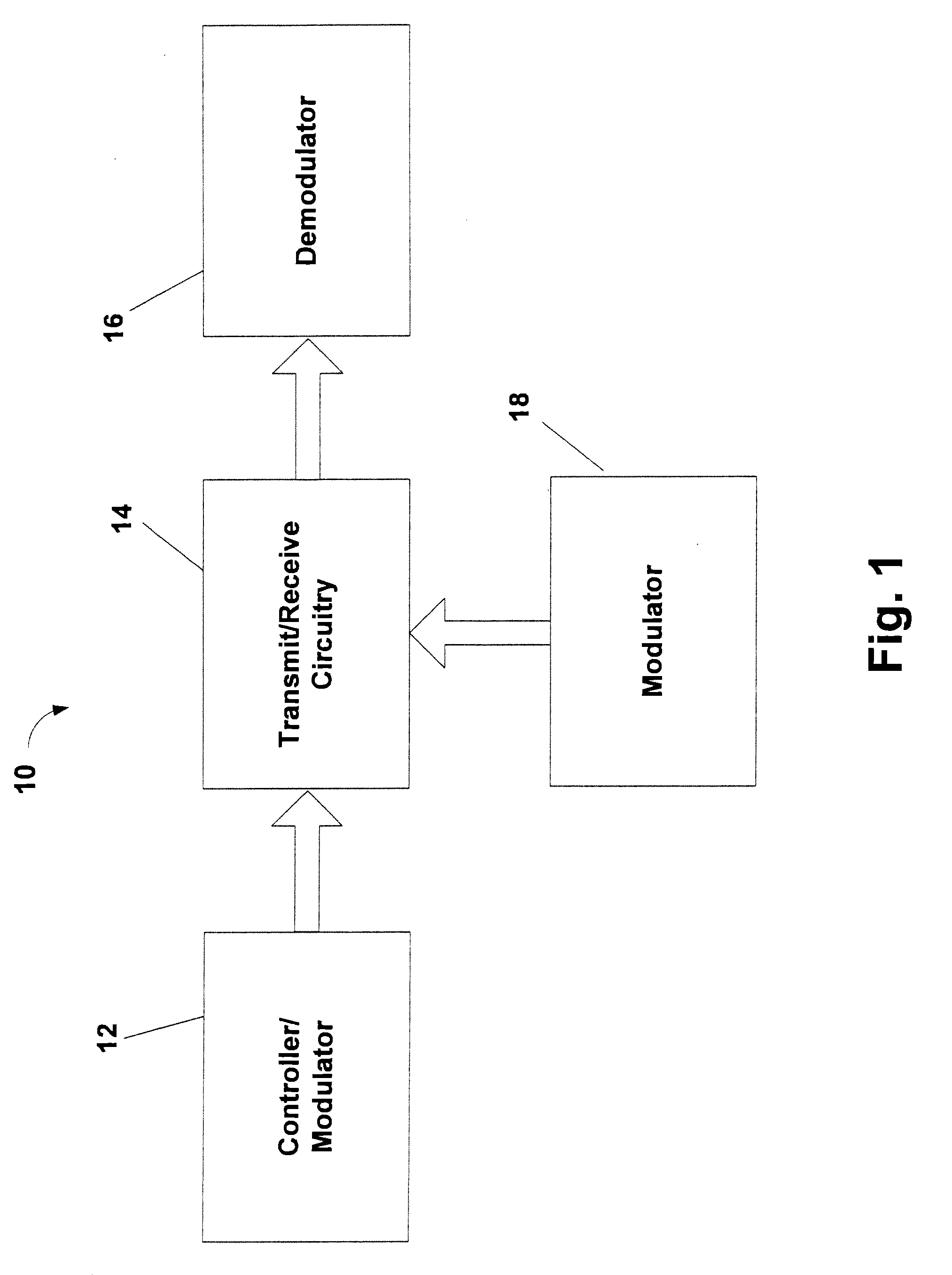
[0037] Although the following description is directed primarily toward telemetry systems in which the bandwidth and Q are variable, embodiments of the present invention may be implemented in a variety of ways and used in a variety of capacities and applications. For example, embodiments of the present invention may be implemented in such a way such that other parameters of the telemetry circuit, such as the power output or transmit distance, for example, are variable. Also, embodiments of the present invention may be used in various applications, such as, for exa...


PUM


Abstract

A programmable telemetry circuit that may be programmed for high bandwidth, low Q; low bandwidth, high Q; or for other parameters. The programmable telemetry circuit may include a first coil; a high impedance path having a first node connected to a first node of the first coil; a low impedance path having a first node connected to the first node of the first coil; a capacitive path having a first node connected to a second node of the first coil; and an input path for coupling signals into the high impedance path, the low impedance path, and the capacitive path. The low impedance path may be connected in parallel with the high impedance path. The capacitive path may form a circuitous path with the high impedance path and the low impedance path. The programmable circuit may be programmed to select the high impedance path or the low impedance path.

Description

BACKGROUND [0001] 1. Field of the Invention [0002] Embodiments of the present invention relate to telemetry systems and, in particular, to remote controlled telemetry systems with variable parameters and to telemetry systems implanted in human bodies in which the bandwidth and Q, among other parameters, are variable. [0003] 2. Description of Related Art [0004] The use of implantable devices to remedy medical conditions is becoming increasingly frequent as the size and cost of such devices shrink. Many people with medical conditions who, in the past, were burdened with the prospect of remaining close to an analytical or treatment device have newfound freedom with implantable devices that allow them to receive the analysis and / or treatment they need from the implantable device. [0005] For example, in the past, many diabetics who have needed blood glucose analysis on a daily basis or even multiple times during a day and who have required insulin injections in response to the analysis h...

Claims


Application Information

Patent Timeline
Patent Type & Authority Applications(United States)
IPC IPC(8): G08C19/16A61N1/372G08C17/04H04B1/04
CPCA61N1/37223
Inventor MORGAN, WAYNE A.HESS, PHILLIP B.
Owner MEDTRONIC MIMIMED INC
Why Eureka
Try Eureka