Antenna Switch Module

a switch module and switch technology, applied in the direction of electrical devices, antennas, coupling devices, etc., can solve the problems of increasing the amount of attenuation between the poles, difficult for this filter to achieve wideband filtering at low loss, and inability to have enough attenuation, etc., to achieve easy reduction of rebound components, reduce filtering loss, and high attenuation

Inactive Publication Date: 2008-03-06
PANASONIC CORP
View PDF6 Cites 31 Cited by
  • Summary
  • Abstract
  • Description
  • Claims
  • Application Information

AI Technical Summary

Benefits of technology

[0013]The present invention provides an antenna switch module including a filter which can reduce filtering loss so as to achieve high attenuation in a wide band at harmonic frequencies.
[0014]The antenna switch module of the present invention includes the filter, an antenna switch circuit and an adjustment line. The filter passes fundamental frequencies and has an attenuation pole. The antenna switch circuit switches antennas matching the fundamental frequencies. The adjustment line is connected between the filter and the antenna switch circuit, and adjusts properties of the fundamental frequencies at the harmonic frequencies. When the filter and the antenna switch circuit are directly connected with each other at a connection point, the adjustment line prevents the impedance when the filter is seen from the connection point and the impedance when the antenna switch circuit is seen from the connection point from becoming complex conjugates of each other at the harmonic frequencies.
[0015]This antenna switch module can easily reduce rebound components between the attenuation poles of the filter at the harmonic frequencies without degrading the amount of attenuation at the attenuation poles, thereby fully attenuating the harmonic components without increasing the number of stages of the filter. For example, fundamental frequency signals amplified by a power amplifier in the front end module of a wireless LAN (Local Area Network) are passed at low loss, and the harmonic components generated by the power amplifier can be removed in a wide band at high attenuation.

Problems solved by technology

However, it is difficult for this filter to achieve wideband filtering at low loss because the filter has ripples in the passband.
Reducing the interval between these poles results in an increase in the amount of attenuation between the poles.
This may deteriorate the amount of attenuation at the attenuation poles or cause a rebound phenomenon between the attenuation poles, thereby making it impossible to have enough attenuation.

Method used


Image

  • Antenna Switch Module
  • Antenna Switch Module
  • Antenna Switch Module

Examples


Embodiment Construction

[0047]An embodiment of the present invention will be described as follows with drawings.

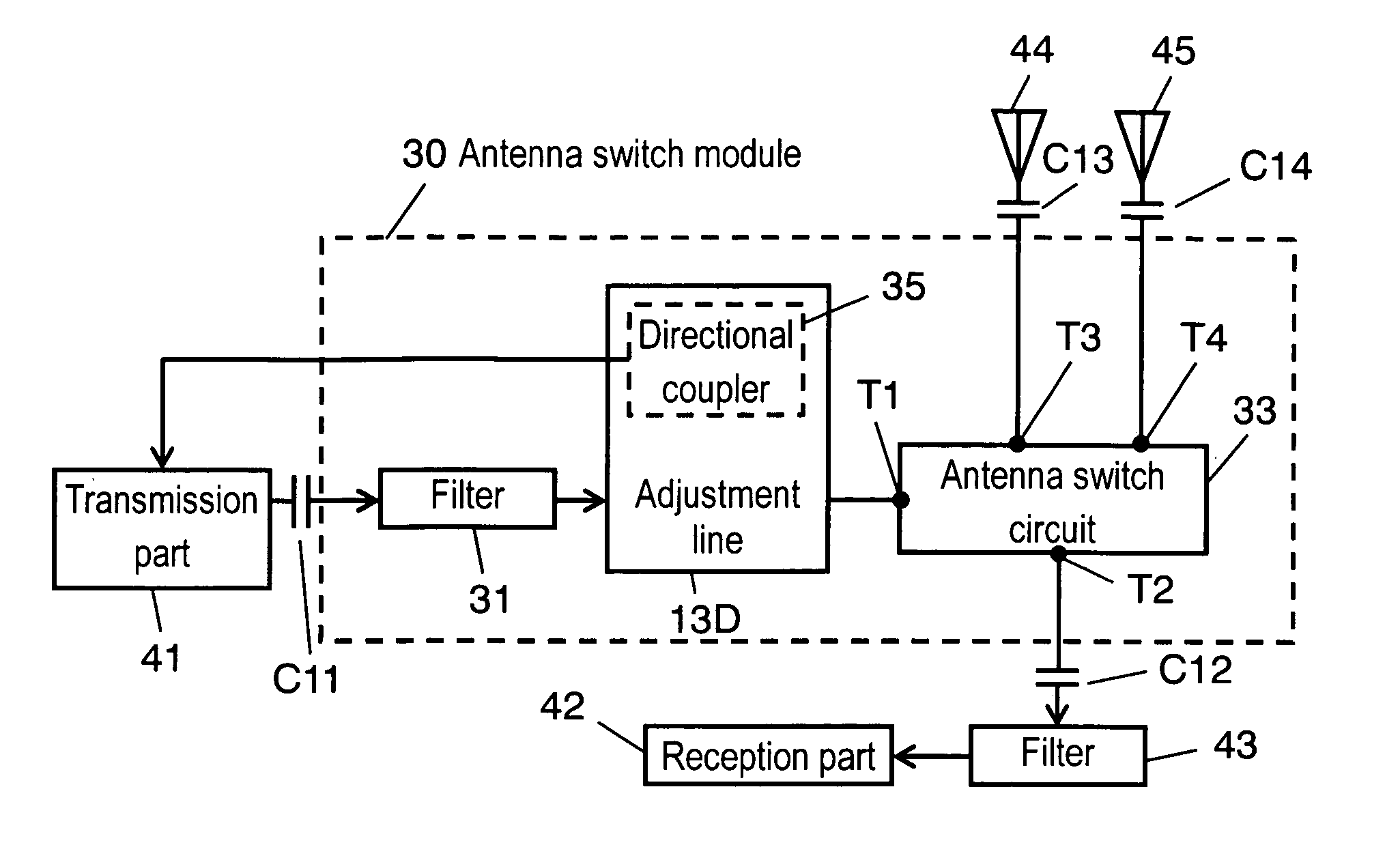
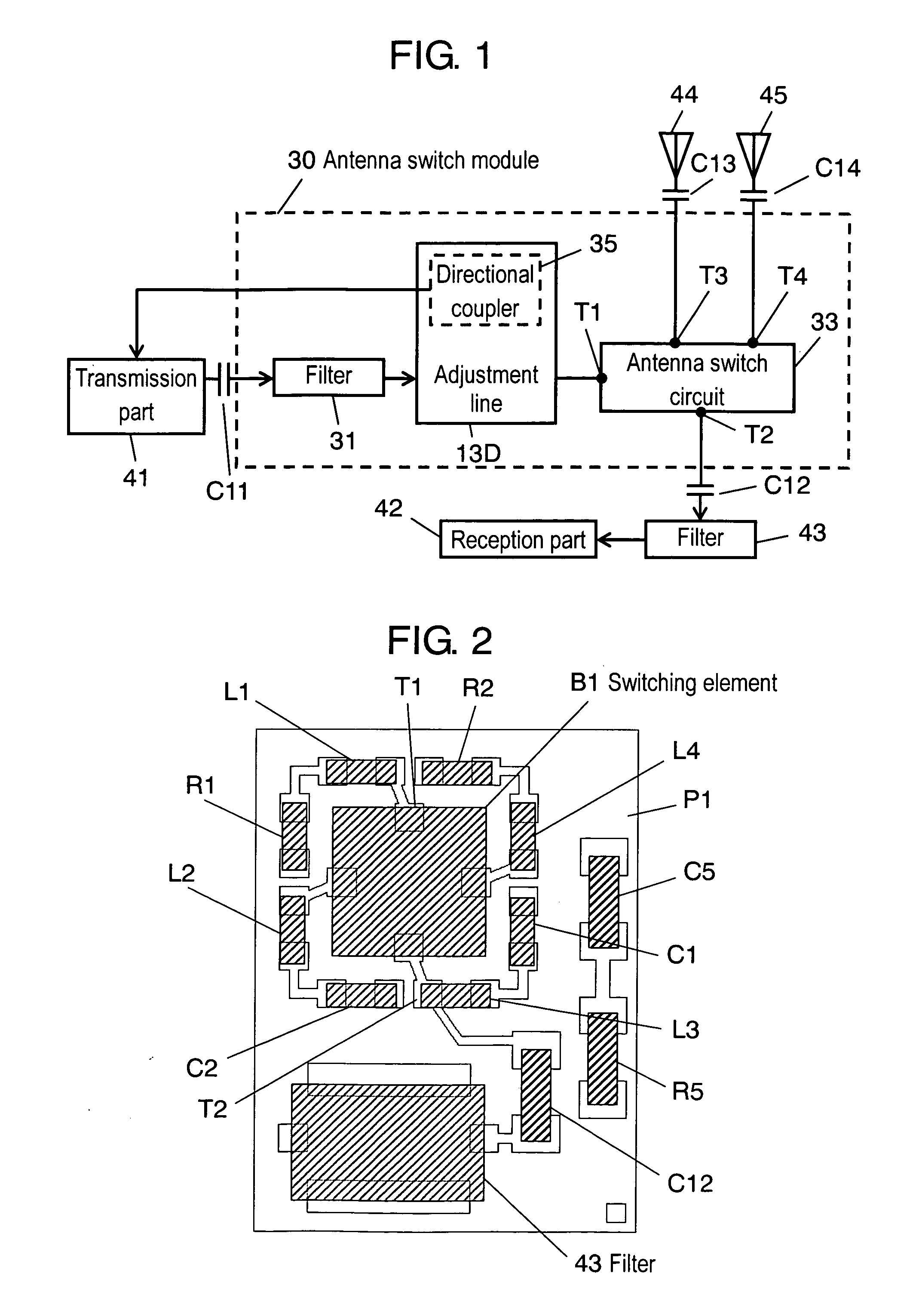
[0048]FIG. 1 is a block diagram showing the structure of a communication device including an antenna switch module of the embodiment of the present invention. In FIG. 1, a communication device includes antenna switch module 30, transmission part 41, reception part 42, filter 43, antennas 44 and 45, and capacitors C11 to C14. Antenna switch module 30 includes antenna switch 33, filter 31 and adjustment line 13D. Adjustment line 13D, together with other components described later, make up directional coupler 35.

[0049]Signals from transmission part 41 are inputted to filter 31 through capacitor C11. Filter 31 is a notch low pass filter which removes unnecessary harmonic signals contained in the signals from transmission part 41. Filter 31 has fundamental frequencies of 4.9 to 5.85 GHz. The second harmonic frequencies are from 9.8 to 11.7 GHz, and the third harmonic frequencies are from 14.7 to 17.55...


PUM


Abstract

An antenna switch module includes a filter which reduces transmission loss so as to achieve high attenuation in a wide band at harmonic frequencies. This antenna switch module includes the filter, an antenna switch circuit and an adjustment line. The filter passes fundamental frequencies and has an attenuation pole. The antenna switch circuit switches antennas. The adjustment line is connected between the filter and the antenna switch circuit. The adjustment line adjusts its length, and when the filter and the antenna switch circuit are directly connected with each other at a connection point, prevents the impedance when the filter is seen from the connection point and the impedance when the antenna switch circuit is seen from the connection point from becoming complex conjugates of each other at the harmonic frequencies.

Description

[0001]This application is a U.S. National Phase Application of PCT International Application PCT / JP2005 / 013031.TECHNICAL FIELD[0002]The present invention relates to an antenna switch module including an antenna switch which switches antennas, and a filter which passes fundamental frequencies and has an attenuation pole.BACKGROUND ART[0003]FIG. 12 shows a block diagram of a conventional communication device including conventional antenna switch module 80. Conventional antenna switch module 80 will be described with FIG. 12. In FIG. 12, the communication device includes antenna switch module 80, transmission part 41, reception part 42, filter 83, antennas 44 and 45, and capacitors C81 to C84.[0004]Conventional antenna switch module 80 includes antenna switch circuit 87 and filter 86. Signals from transmission part 41 are inputted to filter 86 through capacitor 81. Filter 86 passes fundamental frequencies and removes unnecessary signals. Signals outputted from filter 86 are emitted fro...

Claims


Application Information

Patent Timeline
Patent Type & Authority Applications(United States)
IPC IPC(8): H01Q23/00
CPCH01P1/15
Inventor TAMURA, MASAYAFUJIHASHI, YOSHIKUNI
Owner PANASONIC CORP
Why Eureka
Try Eureka