Duplexer and ladder type filter

a technology of duplexers and filters, applied in the direction of impedence networks, electrical equipment, piezoelectric/electrostrictive/magnetostrictive devices, etc., can solve the problems of reducing the mounting area, reducing the attenuation in a wide bandwidth, and no specific measures to improve the characteristic of duplexers, so as to increase the attenuation in the stopband, reduce the capacitance between the receive line and the transmit line, the effect of increasing

Active Publication Date: 2009-08-11
TAIYO YUDEN KK
View PDF25 Cites 25 Cited by
  • Summary
  • Abstract
  • Description
  • Claims
  • Application Information

AI Technical Summary

Benefits of technology

[0026]The present invention has been made in view of the above circumstances and provides a duplexer and a ladder type filter that enables a low loss, a high attenuation, and downsizing.
[0029]According to another aspect of the present invention, there is provided a ladder type filter including: multiple parallel resonators; multiple series resonators; one or more first inductors respectively connected in parallel with one or more series resonators out of the multiple series resonators; and a second inductor connected in series between ground and ground sides of two or more parallel resonators commonly connected, out of the multiple parallel resonators. By providing the first inductors and the second inductor, the attenuation can be increased in the stopband with a low insertion loss. In addition, the second inductor is commonly connected to the two or more parallel resonators, thereby decreasing a desired value of the inductor for forming an attenuation pole in the stopband. This easily realizes downsizing and cost reduction. Further, the first inductors are connected one or more series resonators, thereby suppressing the degradation of attenuation in a wide passband.
[0031]According to another aspect of the present invention, there is provided a duplexer including: a transmit filter and a receive filter connected to a common terminal, and at least one of the transmit filter and the receive filter is a ladder type filter having a series resonator and a parallel resonator; an inductor connected between the parallel resonators and ground in the ladder type filer; a mounting portion mounting a chip where the series resonator and the parallel resonator of the ladder type filter are formed; a receive line provided in the mounting portion to connect the receive filter and a receiving terminal; a transmit line provided in the mounting portion to connect the transmit filter and a transmitting terminal; a common line provided in the mounting portion to connect the common terminal and the receive filter and the transmit filter; and an inductor line provided in the mounting portion to compose the inductor. The inductor line is provided between either the receive line or the transmit line and the common line. The electrostatic coupling and the bridging capacitance between the receive line and the transmit line can be reduced, thereby increasing the attenuation in the stopband.

Problems solved by technology

It is to be noted that in conventional technique 1, however, there is no consideration of the characteristic of a duplexer that includes a filter, and there are no specific measures to improve the characteristic of the duplexer.
However, the attenuation will be degraded drastically in a wide bandwidth.
In such technique, two elements of the inductor L01 and the capacitor C01 are used, thereby making it difficult to reduce the mounting area, in other words, difficult to downsize the duplexer.
Meanwhile, in W-CDMA / UMTS system, it is difficult to obtain the attenuation in the frequency range (the receive bandwidth of the transmit filter and the transmit bandwidth of the receive filter) widely apart from the passband.
However, no inductor is connected to the parallel resonator and the attenuation pole of the resonance in the parallel resonator exists around the passband, thereby making it impossible to ensure the attenuation sufficiently in the frequency range widely apart from the passband.
For this reason, it is difficult to form the inductor with the use of a line pattern in a package in order to reduce the size of the package.
Also, as shown in FIG. 23 of Document 4, in a case where there are two circuits, each of which includes the inductor connected in series with the parallel resonator, there are problems: downsizing is more difficult; and the characteristic is degraded due to the electromagnetic coupling between the two inductors.
Besides, there are no specific measures that improve the characteristic of the duplexer.
However, the attenuation in a wide band is degraded drastically.

Method used


Image

  • Duplexer and ladder type filter
  • Duplexer and ladder type filter
  • Duplexer and ladder type filter

Examples


first exemplary embodiment

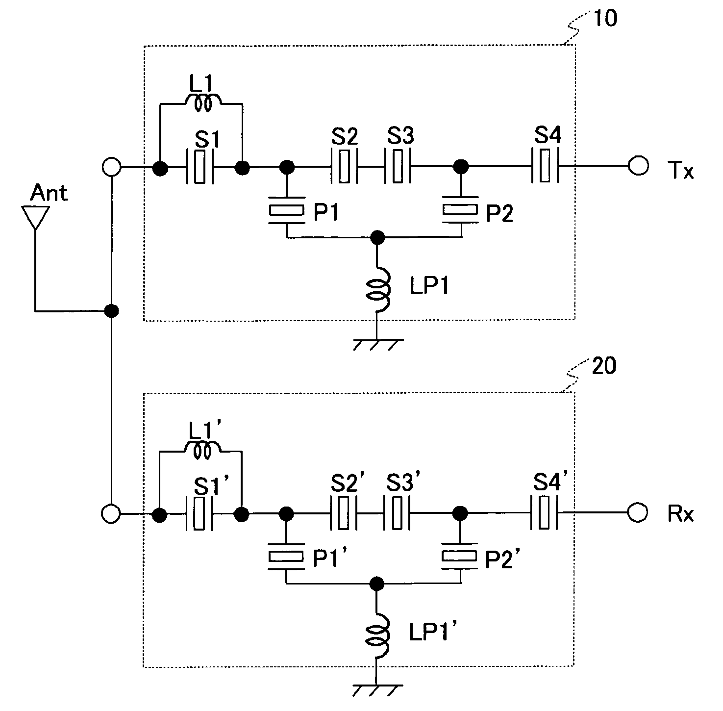
[0110]A first exemplary embodiment of the present invention is an example of a duplexer having the transmit bandwidth of 1920 MHz to 1980 MHz and the receive bandwidth of 2110 MHz to 2170 MHz. FIG. 8A shows a circuit configuration of the duplexer in accordance with the first exemplary embodiment of the present invention. In this duplexer, a transmit filter 10 (first filter) is connected between an antenna terminal Ant and a transmitting terminal Tx. Similarly, a receive filter 20 (second filter) is connected between the antenna terminal Ant and the receiving terminal Rx.

[0111]FIG. 9 shows a circuit configuration of the transmit filter 10. Referring to FIG. 9, the transmit filter 10 is a ladder type filter that includes multiple series resonators S1 through S4 and parallel resonators P1 and P2. In addition, an inductor L1 is connected in parallel with the series resonator S1 arranged closest to the antenna terminal Ant. Further, an inductor LP1 is connected between the parallel reson...

second exemplary embodiment

[0120]A second exemplary embodiment is an example in which the capacitance value of the series resonator arranged closest to the antenna terminal Ant is set smaller than those of other series resonators in the transmit filter 10 and in the receive filter 20, in order to improve the insertion loss more than that obtained in the first exemplary embodiment. In the duplexer having the same configuration as that of the duplexer employed in the first exemplary embodiment, desirable relationship of the series resonators has been studied.

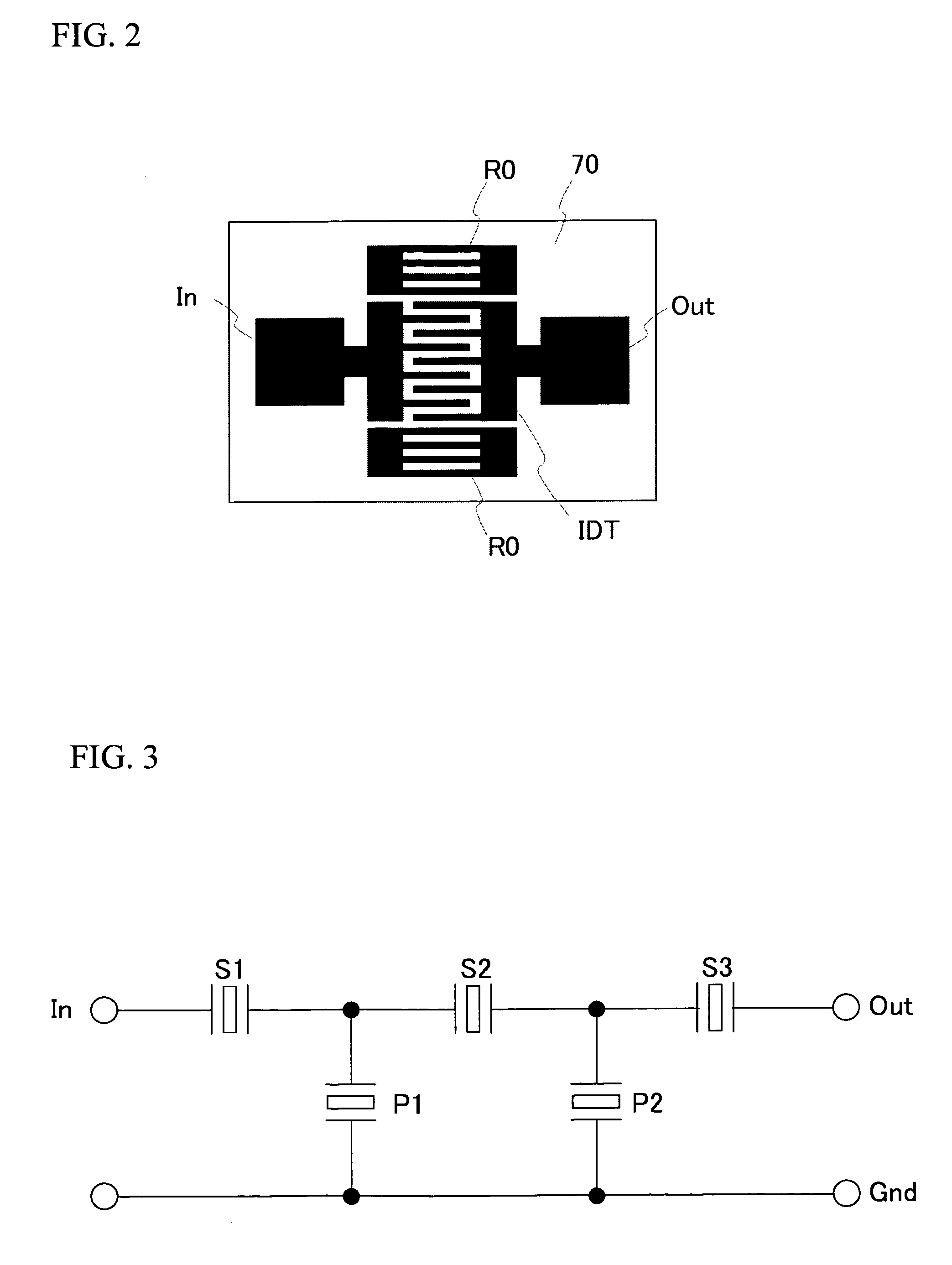
[0121]Firstly, a description will now be given of the definition of the capacitance value of the series resonator in the ladder type filter. FIG. 12 shows a basic segment of the ladder type filter in which one series resonator S and one parallel resonator P are provided. FIG. 13A shows a ladder type filter F1, in which four basic segments of FIG. 12 are arranged between the antenna terminal Ant and the terminal Tx / Rx and connected in a mirror configuration ...

third exemplary embodiment

[0130]FIG. 18A shows a circuit configuration of the duplexer in accordance with a third exemplary embodiment of the present invention. The inductors are not connected to the series resonators S1 through S4 in a transmit filter 10a with respect to the duplexer employed in first exemplary embodiment of FIG. 8A. In addition, a matching circuit 30a is connected between the transmit filter 10a and the antenna terminal Ant. In the third exemplary embodiment, the same components and configurations as those of FIG. 8A have the same reference numerals and a detailed explanation will be omitted.

[0131]FIG. 18B shows a circuit configuration of a variation of the duplexer in accordance with the third exemplary embodiment of the present invention. The inductors are not connected to the series resonators S1′ through S4′ in a receive filter 20a with respect to the duplexer of FIG. 8A employed in first exemplary embodiment. In addition, a matching circuit 30b is connected between the receive filter ...


PUM


Abstract

A duplexer includes an antenna terminal, a first filter connected to the antenna terminal, and a second filter connected to the antenna terminal. At least one of the first filter and the second filter is a ladder type filter in which a parallel resonator and multiple series resonators are included, one or more first inductors are respectively connected in parallel with one or more series resonators out of the multiple series resonators, and one of the one or more first inductors is connected in parallel with one of the multiple series resonators that is arranged closest to the antenna terminal.

Description

BACKGROUND OF THE INVENTION[0001]1. Field of the Invention[0002]This invention generally relates to duplexers and ladder type filters, and more particularly, to a duplexer and a ladder type filter in which an inductor is connected in series with a parallel resonator or an inductor is connected in parallel with a series resonator.[0003]2. Description of the Related Art[0004]In recent years, mobile telephones and mobile information terminals have become widespread rapidly, with the advancements of mobile communications systems. For example, the mobile telephone terminals communicate at high-frequency bands such as 800 MHz to 1.0 GHz and 1.5 GHz to 2.0 GHz. A device for the mobile communication system often employs a high-frequency filter having a resonator or antenna duplexer having the high-frequency filter.[0005]As a resonator for use in the afore-mentioned filter, there are Surface Acoustic Wave (SAW) Resonator and Film Bulk Acoustic Resonator (FBAR). The configuration of the above...

Claims


Application Information

Patent Timeline
Patent Type & Authority Patents(United States)
IPC IPC(8): H03H9/70H03H9/54H03H9/72H03H9/64
CPCH03H9/605H03H9/725H03H9/706
Inventor NISHIHARA, TOKIHIROINOUE, SHOGOMATSUDA, TAKASHIUEDA, MASANORIIWAKI, MASAFUMITANIGUCHI, SHINJIENDO, GO
Owner TAIYO YUDEN KK
Why Eureka
Try Eureka