Inkjet recording apparatus and inkjet recording method

a recording apparatus and inkjet technology, applied in the direction of measuring apparatus components, duplicating/marking methods, instruments, etc., can solve the problems of large energy load, system instability, and marked decline in print quality, and achieve high-quality printing and improve the solvent absorption rate

Inactive Publication Date: 2008-03-06
FUJIFILM CORP
View PDF8 Cites 53 Cited by
  • Summary
  • Abstract
  • Description
  • Claims
  • Application Information

AI Technical Summary

Benefits of technology

[0010]The present invention has been contrived in view of the aforementioned circumstances, an object thereof being to provide an inkjet recording apparatus which is capable of high quality printing by raising the solvent absorption rate achieved by an absorbing body.

Problems solved by technology

In high-quality inkjet printing, if wrinkling (“called cockling”) of the paper occurs as a result of a deposited solvent permeating into the paper, then the print quality declines markedly.
In response to this problem, there is a known method which evaporates (dries) the solvent by means of heating, but this method requires a large load of energy, and may lead to instability of the system (for example, liquid droplet ejection failures as a result of the ink drying in the nozzle sections).
In Japanese Patent Application Publication No. 2005-161610, Japanese Patent Application Publication No. 2005-271401 and Japanese Patent Application Publication No. 2006-82428, the holes formed in the contact portion of the surface of the absorbing body are formed to have a small opening diameter so that the coloring material does not enter into the absorbing body; however, if this technique is applied to a case where a coloring material aggregate is formed by causing the ink to react with a treatment liquid so that the coloring material in the ink aggregates, then situations may arise where the coloring material aggregate becomes blocked in the holes of the absorbing material, and hence there is a possibility that the absorption rates of the treatment liquid and the ink solvent (the solvent absorption rate) may decline dramatically, causing marked deterioration of the print quality.

Method used


Image

  • Inkjet recording apparatus and inkjet recording method
  • Inkjet recording apparatus and inkjet recording method
  • Inkjet recording apparatus and inkjet recording method

Examples


Embodiment Construction

General Composition of Inkjet Recording Apparatus

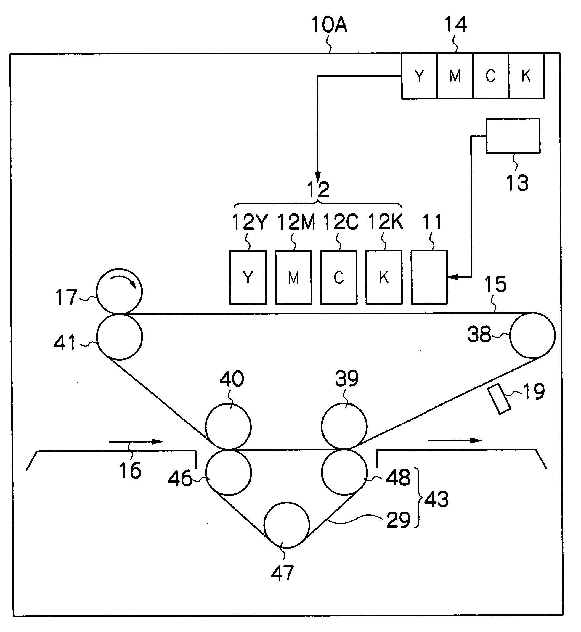
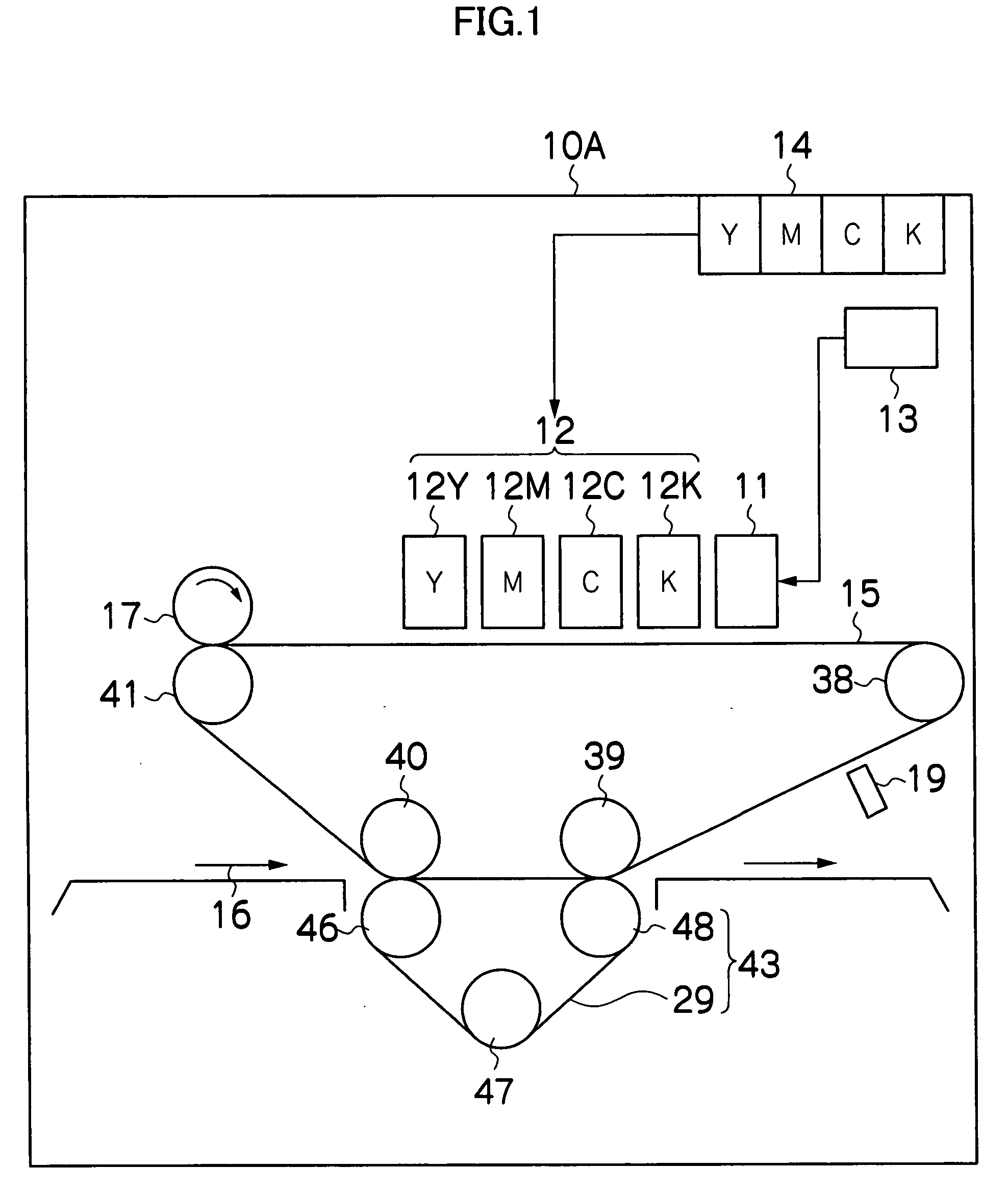
[0040]FIG. 1 is a general schematic drawing of an intermediate transfer type of an inkjet recording apparatus which is one embodiment of an inkjet recording apparatus relating to the present invention. As shown in FIG. 1, this inkjet recording apparatus 10A comprises an inkjet recording head (hereinafter, called “head”) 11 which is provided to correspond to a treatment liquid 28 which does not contain coloring material, and a print unit 12 having a plurality of ink heads 12K, 12C, 12M and 12Y provided to correspond to respective inks 27 (first liquid) which contain respective coloring materials of black (K), cyan (C), magenta (M) and yellow (Y). Furthermore, an absorbing body 17 for absorbing the solvent is provided. Moreover, an endless intermediate transfer body 15 which is spanned about a plurality of rollers (38 to 41) is also provided. A transfer body cleaning unit 19 is provided as a cleaning device for the intermediate transfer...


PUM

PropertyMeasurementUnit
particle sizeaaaaaaaaaa
opening diameteraaaaaaaaaa
diameteraaaaaaaaaa

Abstract

The inkjet recording apparatus has: an ink droplet ejection device which ejects a droplet of an ink containing a coloring material; a treatment liquid deposition device which deposits a treatment liquid that causes the coloring material contained in the ink to aggregate so as to create a coloring material aggregate; and an absorbing body which absorbs a solvent of a mixed liquid including the ink ejected as the droplet by the ink droplet ejection device and the treatment liquid deposited by the treatment liquid deposition device, wherein solvent absorption holes having an opening diameter larger than a spreading width of the coloring material aggregate in the mixed liquid on a surface of a recording body are formed in a surface of the absorbing body.

Description

BACKGROUND OF THE INVENTION[0001]1. Field of the Invention[0002]The present invention relates to an inkjet recording apparatus, and more particularly, to an inkjet recording apparatus which is capable of inkjet printing of high quality by improving the solvent absorption rate by means of an absorbing body.[0003]2. Description of the Related Art[0004]In high-quality inkjet printing, if wrinkling (“called cockling”) of the paper occurs as a result of a deposited solvent permeating into the paper, then the print quality declines markedly. In response to this problem, there is a known method which evaporates (dries) the solvent by means of heating, but this method requires a large load of energy, and may lead to instability of the system (for example, liquid droplet ejection failures as a result of the ink drying in the nozzle sections).[0005]In response to this, Japanese Patent Application Publication No. 2005-161610, Japanese Patent Application Publication No. 2005-271401 and Japanese...

Claims


Application Information

Patent Timeline
Patent Type & Authority Applications(United States)
IPC IPC(8): B41J2/04
CPCB41J2/0057B41J2202/20B41J2002/14459B41J2/2114B41M5/0017B41M7/00B41M7/0018
Inventor YAMANOBE, JUN
Owner FUJIFILM CORP
Why Eureka
Try Eureka