Image adjustment derived from optical imaging measurement data

Active Publication Date: 2008-03-06
CARL ZEISS MEDITEC INC
View PDF13 Cites 106 Cited by
  • Summary
  • Abstract
  • Description
  • Claims
  • Application Information

AI Technical Summary

Benefits of technology

[0011]In accordance with the present invention, a method and apparatus is provided for alignment of scan lines relative to the position of the eye. The image of the eye derived from the scan lines is improved by minimizing misalignment. One means for implementing this improvement is to build the image using a scan pattern comprised of pairs of crossed B-scans to build the image and detecting misalignment for each B-scan or B-scan pair and correctly aligning the image data prior to display. One means for detecting misalignment is by finding a landmark of a structural feature within the measurement data. In the anterior chamber, a structural feature of interest is the cornea. The preferred landmark is the vert

Problems solved by technology

Eye movement is known to generate artifacts in the displayed image.
In current AC-OCT machines, the center of scan pattern is usually imperfectly aligned with the corneal vertex because of difficulties of attaining and maintaining subject alignment.
Decentricity errors ar

Method used


Image

  • Image adjustment derived from optical imaging measurement data
  • Image adjustment derived from optical imaging measurement data
  • Image adjustment derived from optical imaging measurement data

Examples


Embodiment Construction

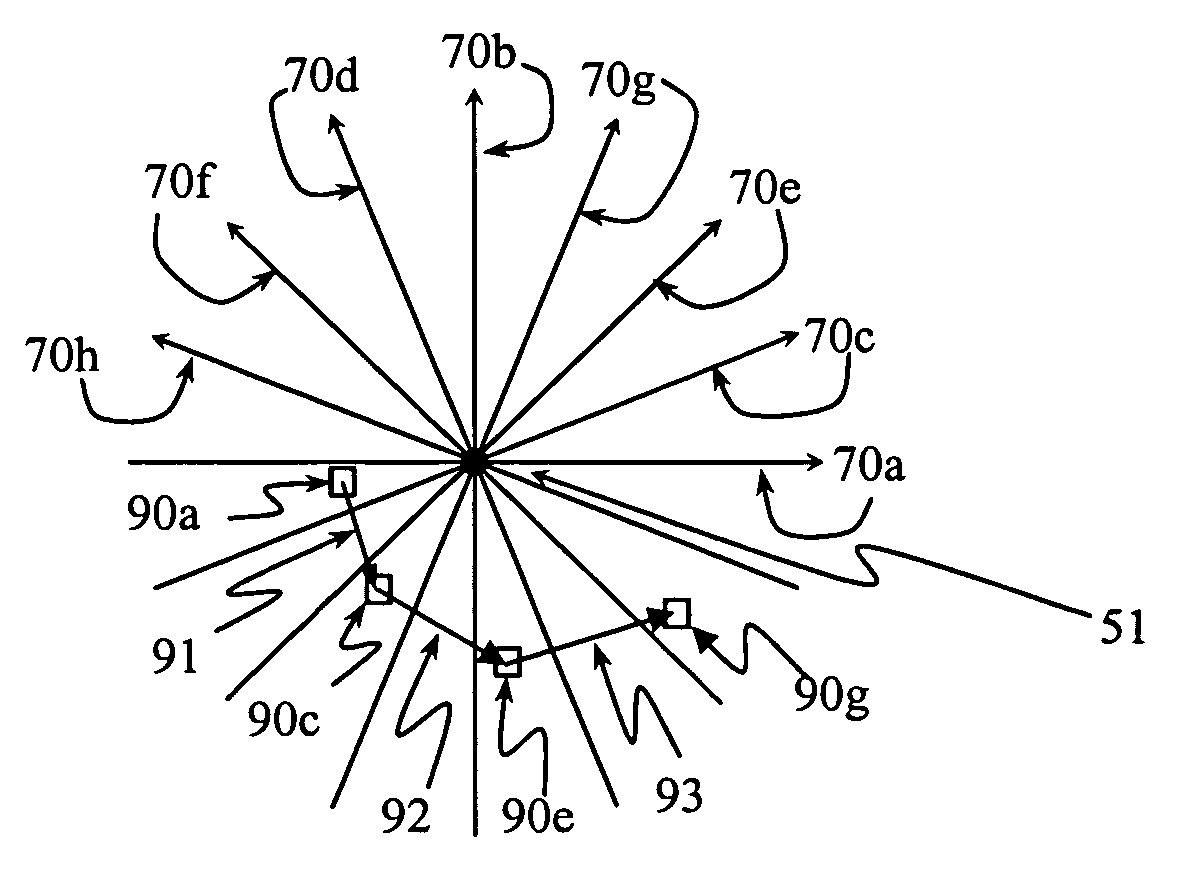
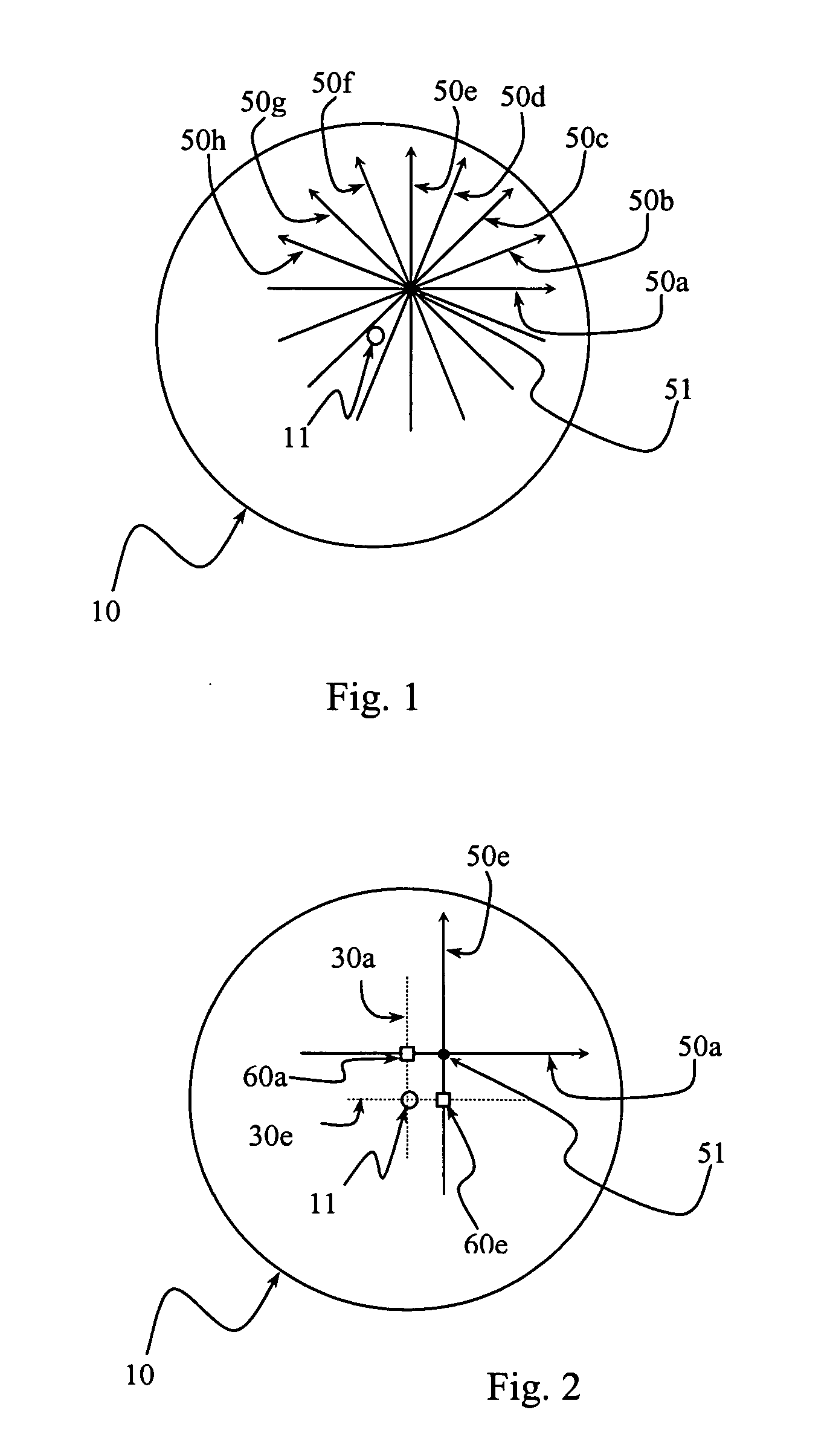
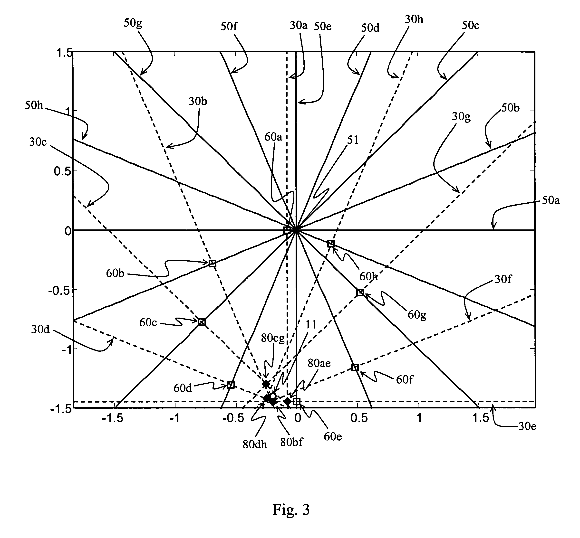
[0027]Anterior Chamber Optical Coherence Tomography (“AC-OCT”) is a state-of-art technology for anterior chamber imaging. AC-OCT can produce a corneal thickness map (Pachymetry map). The Pachymetry map is generally derived from a plurality of B-scans, though, there is no reason that this could not be derived from any sufficiently densely placed collection of scan lines. Most commonly, a B-scan is a collection of scan lines within a plane. A B-scan display is often called a tomogram. The tomogram is derived from measurement data in depth along scan lines and in breadth across the scan plane (the B-scan). AC-OCT measurement data is typically collected along scan lines, where the lines extend from the diagnostic instrument into the eye, with the lines collected across a plane (B-scan).

[0028]FIG. 1 illustrates, in projection, a typical AC-OCT scan pattern for measuring corneal thickness. This scan pattern is a fan of B-scans intersecting at a common center 51. For more uniform resolutio...


PUM


Abstract

A method and apparatus for imaging within the eye is provided whereby a component of eye position is detected using optical imaging data. Tracking eye position over time and correctly registering imaging data for scan locations or using eye position to detect decentration achieves improved imaging. In one embodiment, essentially perpendicular B-scans are imaged sequentially and the corneal arc within each B-scan is analyzed to determine the vertex of the eye. The eye vertex is tracked over pairs of perpendicular B-scans to determine eye motion. In another embodiment, the decentration in the Pachymetry map is removed by correcting for the misalignment of the center of the Pachymetry map and the actual location of the corneal vertex.

Description

TECHNICAL FIELD OF THE INVENTION[0001]The present invention relates to optical medical imaging, and in particular to systems that are adapted to perform Optical Coherence Tomography (“OCT”), especially as adapted to Anterior Chamber (“AC”) imaging in the eye and methods and apparatuses for monitoring and adapting to eye motion in such imaging systems.BACKGROUND OF THE INVENTION[0002]An optical coherence tomography (“OCT”) apparatus is used to perform micron-resolution, cross-sectional imaging of biological tissue. The OCT device uses a light source to illuminate a sample and an interferometer and detector to measure the path length to a reflector in the sample by interference between the light reflected from the sample and a reference light beam. The quality of an OCT image, and the accuracy and reliability of subsequent biometric measurements, depend on proper alignment of the scan lines and / or B-scans of OCT measurement data from which the image is derived.[0003]The proper alignme...

Claims


Application Information

Patent Timeline
IPC IPC(8): A61B3/10
CPCA61B3/102A61B3/1225A61B3/113
Inventor MEYER, SCOTTCHEN, XUNCHANGCHIN, RODNEY P.
Owner CARL ZEISS MEDITEC INC
Why Eureka
Try Eureka