Aberration Correction Device, Aberration Correction Method And Optical Pickup

a technology of aberration correction and optical pickup, which is applied in the field of aberration correction devices, aberration correction methods and optical pickups, can solve the problems of inability to form divided areas suitable for two kinds of aberration, inability to effectively correct coma aberration, and inability to ensure an appropriate converging function for correcting aspherical aberration for such a siz

Inactive Publication Date: 2008-03-06
PIONEER CORP
View PDF8 Cites 7 Cited by
  • Summary
  • Abstract
  • Description
  • Claims
  • Application Information

AI Technical Summary

Benefits of technology

[0009] When several kinds of aberrations need to be corrected as in the above-discussed image-formation optical system, if an aberration correction is performed using an electro-optic effect of the aforementioned liquid ...

Problems solved by technology

Moreover, as disclosed in patent document 1, when one transparent electrode in a liquid crystal panel consisting of a pair of transparent electrodes is divided to satisfy two kinds of aberration corrections, it would be impossible to form divided areas suitable for two kinds of aberration.
In this way, if a circular divided area having a converging function is set at a size capable of correcting a spherical aberration, it would be impossible to form a divided area capable of effectively correcting a coma aberration.
On the other hand, if a circ...

Method used


Image

  • Aberration Correction Device, Aberration Correction Method And Optical Pickup
  • Aberration Correction Device, Aberration Correction Method And Optical Pickup
  • Aberration Correction Device, Aberration Correction Method And Optical Pickup

Examples


Embodiment Construction

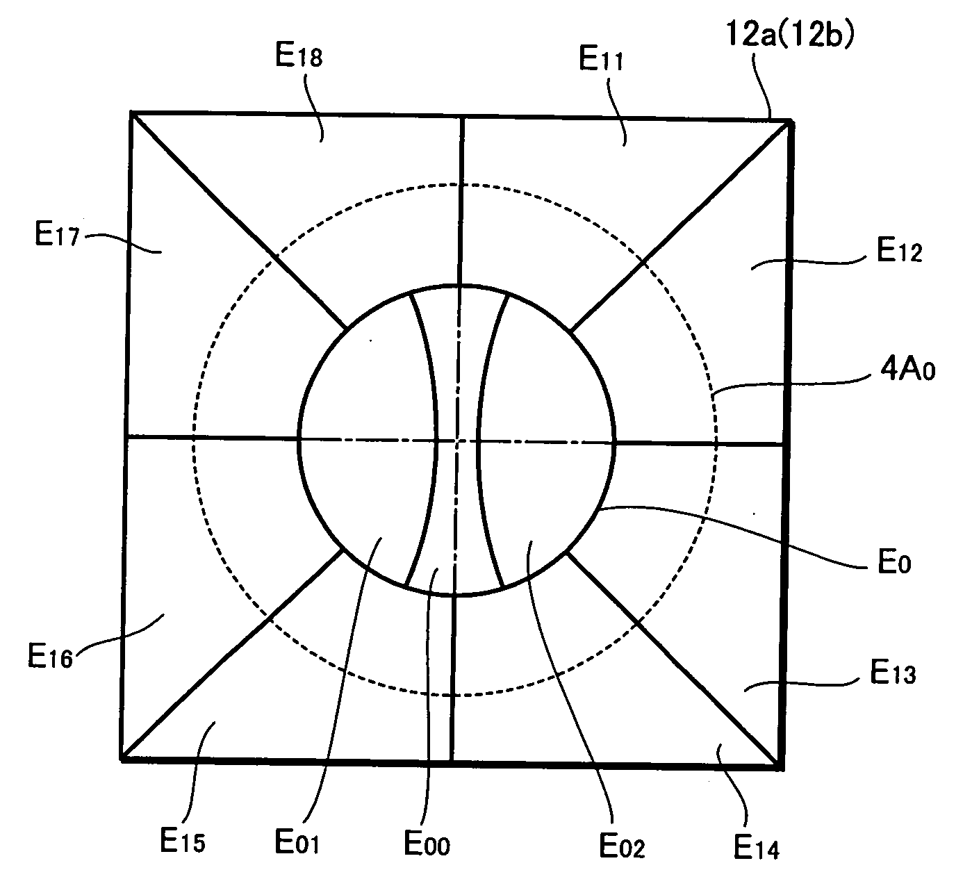
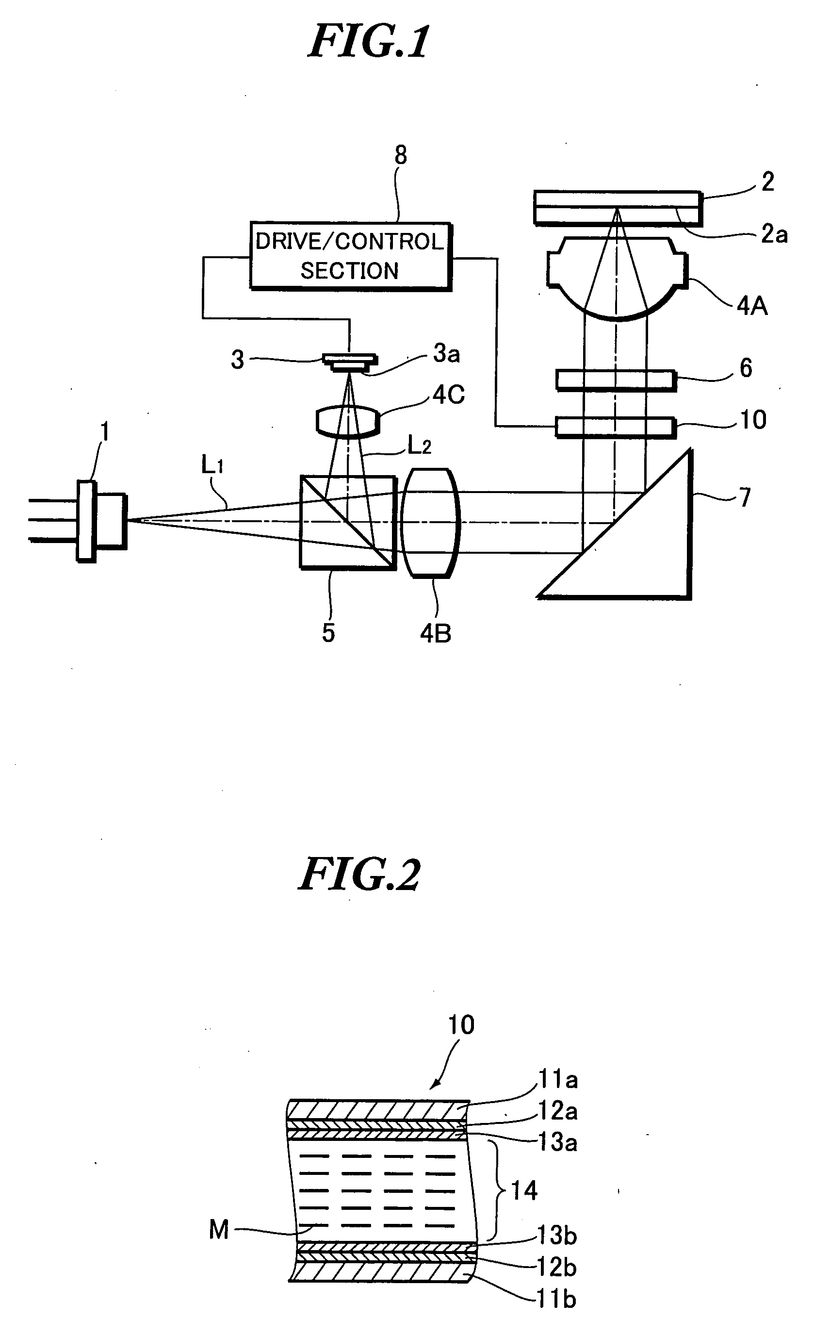
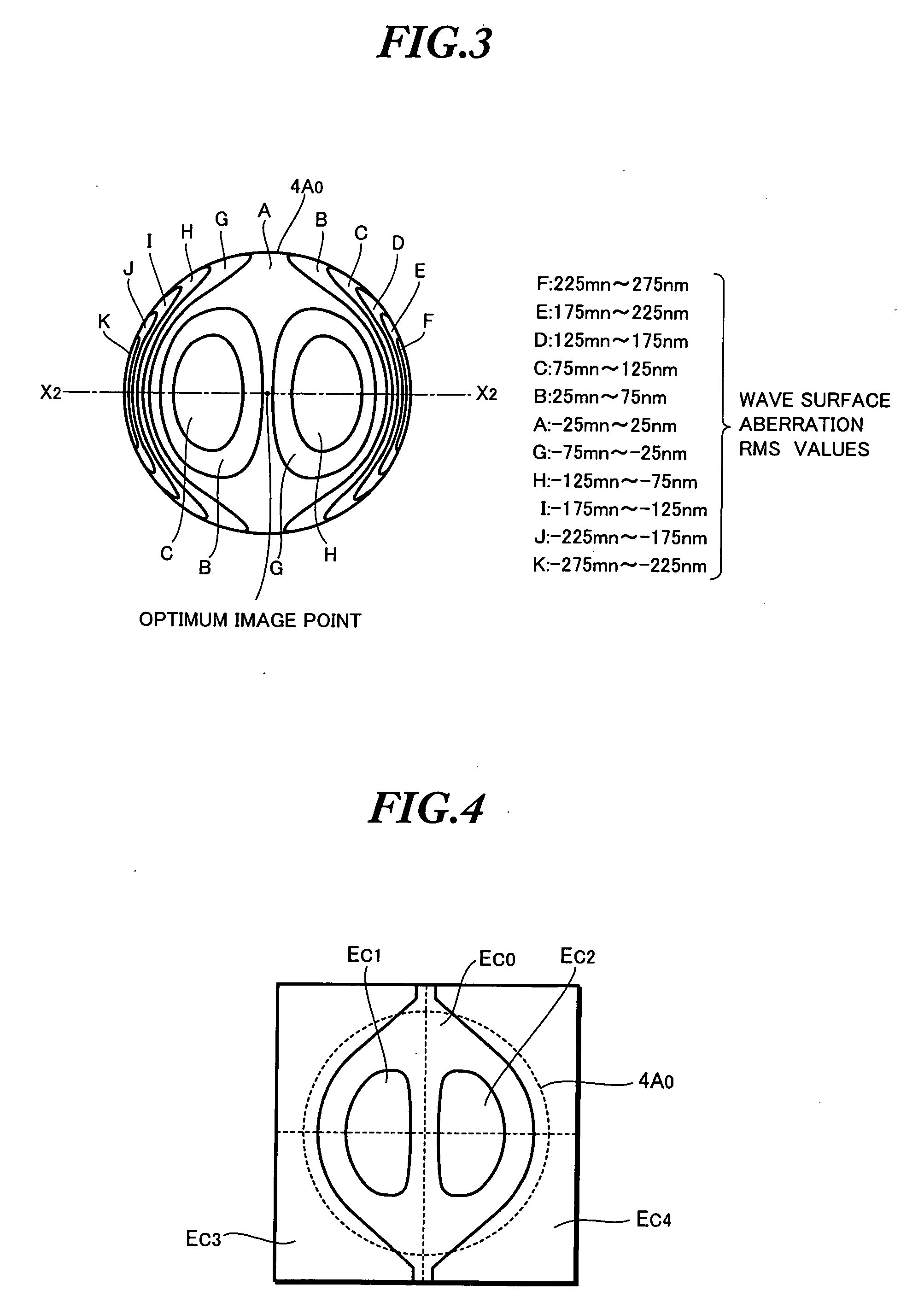
[0032] Next, description will be given to explain embodiments of the present invention with reference to the accompanying drawings. However, since the aberration correction device and the aberration correction method according to the embodiments of the present invention are suitable to be used with an optical pickup, the following description will be based on examples of their applications to an optical pickup. On the other hand, the aberration correction device and the aberration correction method according to the embodiments of the present invention are by no means to be limited to these examples. Moreover, although the following description will be based on a liquid crystal panel which serves as an example of an electro-optic panel of an aberration correction device, the electro-optic panel according to the present invention should not be limited to liquid crystal panel, provided that the electro-optic panel is comprised of a pair of transparent electrodes, capable of effecting a...


PUM


Abstract

The present invention is to provide an improved aberration correction device formed by inserting an electro-optic panel such as a liquid crystal panel in an image-formation optical system to correct aberrations in the image-formation optical system, characterized in that such a correction device is capable of correcting three or more kinds of aberrations using only one electro-optic panel. Divided areas concerning coma aberration correction and divided areas concerning astigmatism correction are formed in one of the transparent electrodes of the electro-optic panel, while the rest of divided areas concerning coma aberration correction and divided areas concerning spherical aberration correction are formed in the other of the transparent electrodes. In this way, it is possible to form divided areas divided into electrode patterns suitable for correcting various aberrations, simplify as much as possible the electrode structure of the transparent electrodes consisting of the divided areas, thereby simplifying a control of voltages to be applied to the divided areas.

Description

TECHNICAL FIELD [0001] The present invention relates to an aberration correction device, an aberration correction method and an optical pickup. BACKGROUND TECHNIQUE [0002] Conventionally, to dynamically correct aberration in an image-formation optical system, there has been known an aberration correction device using a liquid crystal panel. Such an aberration correction device is fabricated in a manner such that transparent electrodes of its liquid crystal panel are formed by virtue of divided areas having aberration correction patterns, and aberration correction is performed by providing a phase difference corresponding to a divided area to a light beam passing through the liquid crystal panel, by virtue of an electro-optic effect of the liquid crystal panel. [0003] Such an aberration correction device is used in an image-formation optical system of an optical pickup which converges a light beam emitted from a light source on to a recording surface of an optical information recordi...

Claims


Application Information

Patent Timeline
IPC IPC(8): G02F1/29G02F1/061G02F1/13G02F1/1343G11B7/125G11B7/135G11B7/1369G11B7/1392
CPCG02F1/061G02F1/134309G02F2203/18G11B7/13927G11B7/0956G11B7/1369G11B7/0948
Inventor OGASAWARA, MASAKAZUFUJINOKI, SHINICHI
Owner PIONEER CORP
Why Eureka
Try Eureka