Lamp transformer

Inactive Publication Date: 2008-03-06
GENERAL ELECTRIC CO
View PDF27 Cites 15 Cited by
  • Summary
  • Abstract
  • Description
  • Claims
  • Application Information

AI Technical Summary

Problems solved by technology

One drawback associated with potting of the transformer is the necessary step of characterization of the transformer subsequent to potting.

Method used


Image

  • Lamp transformer
  • Lamp transformer
  • Lamp transformer

Examples


Embodiment Construction

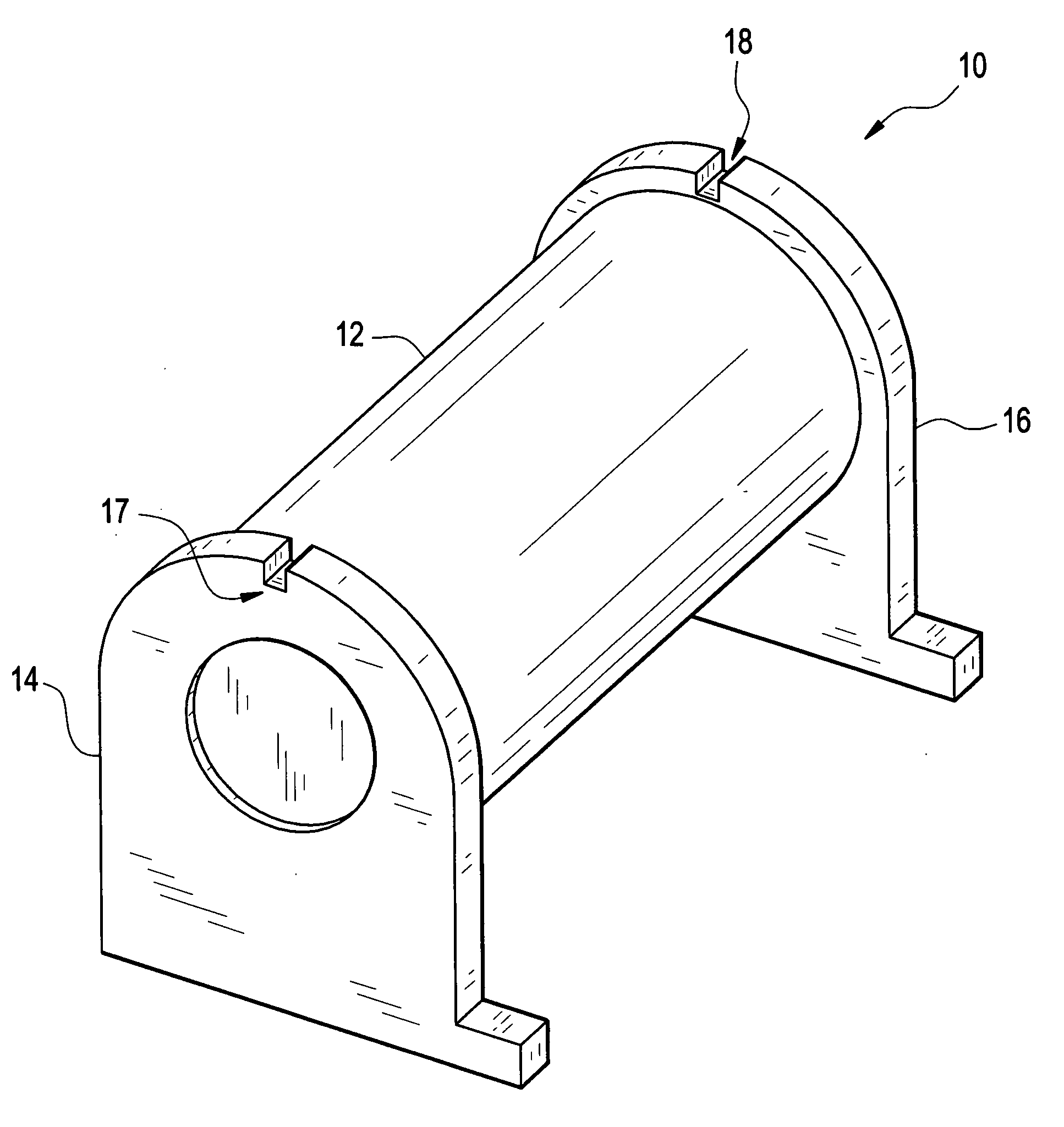
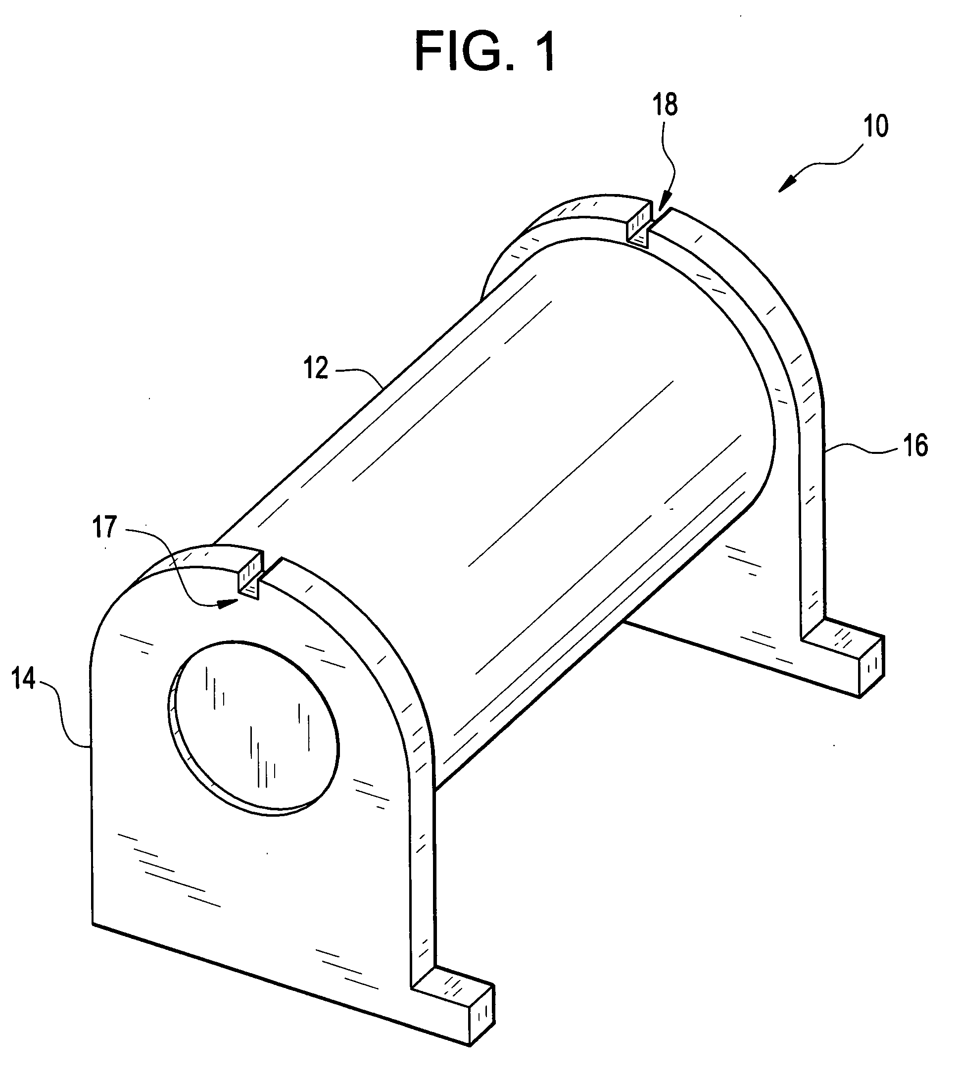
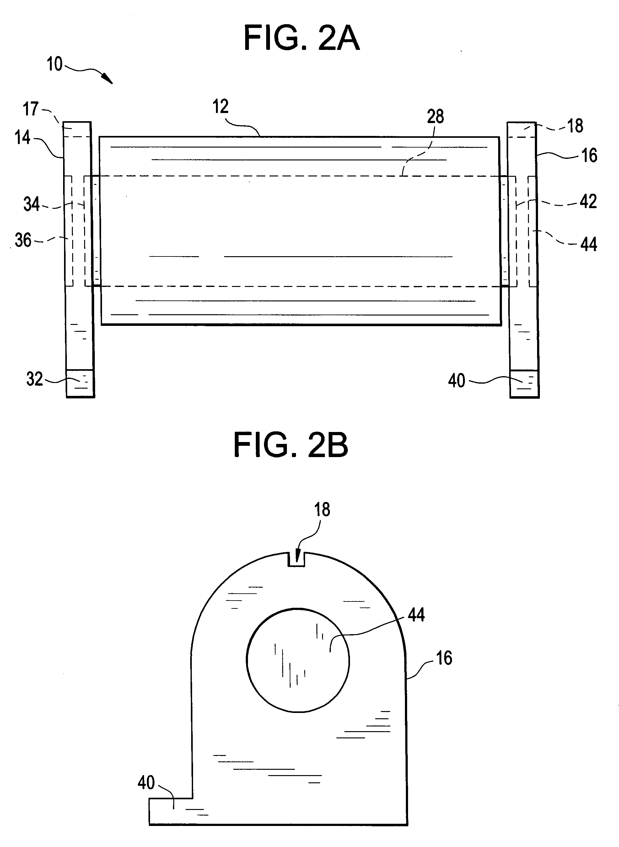
[0030]A high voltage transformer and an associated igniter module for a gas discharge lamp finds particular application in an automotive lamp product, although one of ordinary skill in the art will appreciate that the teachings herein may have application in related products. The modular design comprises a lead frame or printed circuit board (PCB) including low voltage electronic components and a high voltage core transformer substantially covered in a high voltage, insulative potting material. The high voltage core transformer is mounted on the lead frame by means of a carrier. Notably, for purposes of this disclosure, low voltage refers to voltages equal to or less than approximately 1 kV and high voltage refers to voltages greater than approximately 1 kV, for example 30 kV. However, this disclosure is not limited to these specific voltages.

[0031]Potting of the high voltage core transformer may be completed before or after the transformer is attached to the lead frame. Pre-potting...


PUM


Abstract

Disclosed is a lamp transformer and method of assembling a lamp transformer within an igniter module or housing. The lamp transformer comprises a potted bar core transformer; and a carrier attached to the potted bar core transformer, the carrier adapted to position the potted bar core transformer on a pc board and / or within a housing at a predetermined location. In addition, disclosed is a transformer winding and potting method utilizing a transformer carrier.

Description

CROSS-REFERENCE TO RELATED PATENTS AND APPLICATIONS[0001]This application is a Continuation-In-Part of U.S. Utility patent application Ser. No. 11 / 513,777 filed on Aug. 31, 2006 and entitled “LAMP TRANSFORMER,” the entirety of which is incorporated herein by reference.BACKGROUND OF THE INVENTION[0002]This disclosure relates to a high voltage igniter module used to ignite a lamp, for example a HID (High Intensity Discharge) lamp. Specifically, the disclosure relates to a mechanical design of a high voltage transformer and the associated igniter module.[0003]Conventionally, high voltage igniter circuits are used to start HID lamps, such as an automotive lamp or headlight. The igniter circuit typically includes a lead frame or pc board and a transformer where the lead frame carries electrical components to produce a high voltage ignition signal. In addition, the lead frame may provide electrical connection points to power the ignition circuit and deliver the high voltage ignition signa...

Claims


Application Information

Patent Timeline
Patent Type & Authority Applications(United States)
IPC IPC(8): F23Q13/00H01J9/00H05K7/00F21Y101/00
CPCF21S48/1109H01F27/022H01F27/027H01F2027/065H01F38/08H01F41/005H01F27/06F21S41/192
Inventor VARGA, VIKTOR KAROLYROBERTS, BRUCE
Owner GENERAL ELECTRIC CO
Why Eureka
Try Eureka