Resonance converter and synchronous rectification driving method thereof

a synchronous rectification and driving method technology, applied in the direction of dc-dc conversion, power conversion systems, energy industry, etc., can solve the problems of insufficient adaptive ability, circuits that cannot operate properly and safely, and inability to achieve best control of synchronous rectification transistors

Active Publication Date: 2008-03-06
DELTA ELECTRONICS INC
View PDF3 Cites 76 Cited by
  • Summary
  • Abstract
  • Description
  • Claims
  • Application Information

AI Technical Summary

Benefits of technology

[0021]It is therefore an aspect of the present invention to provide a resonance converter and a synchronous rectification driving method thereof. The resonance converter includes a switch circuit having at least two first switches, a resonance circuit having a resonance frequency, a transformer, and a full-wave rectification circuit having two second switches each of which has a drain and a source and generates a channel resistance voltage when a current flows through the drain and the source. The synchronous rectification driving method includes steps as follow. When an operating frequency of the resonance converter is less than the resonance frequency and the resonance converter is coupled to a light load, a constant width pulse determined by resonance parameters of the resonance circuit is used to drive the second switches of the full-w...

Problems solved by technology

Otherwise, the phenomena occur that the synchronous rectification transistors Q1 and Q2 are turned on at the same time and the secondary coils ns1 and ns2 short-circuit, so that the circuit would not be able to operate properly and safely.
But the disadvantage is that the adaptive a...

Method used


Image

  • Resonance converter and synchronous rectification driving method thereof
  • Resonance converter and synchronous rectification driving method thereof
  • Resonance converter and synchronous rectification driving method thereof

Examples


first embodiment

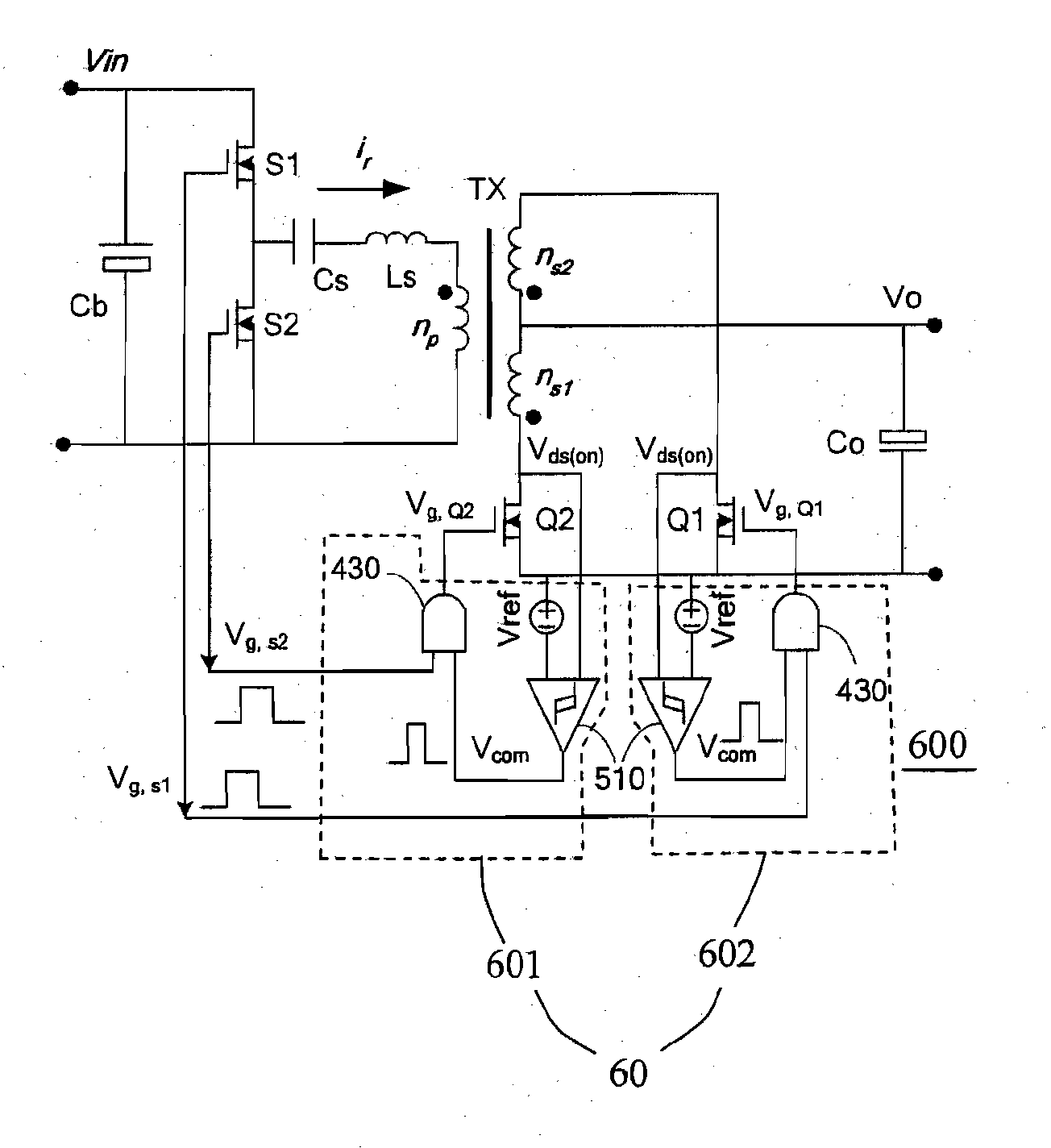
[0031]Please refer to FIG. 6, which is a circuit diagram showing a synchronous rectification scheme of an LLC series resonance converter according to the present invention. In FIG. 6 and FIG. 1, identical circuit devices are given identical graphical symbols so that it is unnecessary to go into details. It is noted that although composed of a half-bridge circuit having only a bridge arm, the input stage of the switch circuit can be similarly composed of a full-bridge circuit having two bridge arms. Additionally, although the transistor switches are used as the switching devices, it does not influence that the switches are used to define various variants of the upperseat concept in the circuits of the embodiments. Furthermore, a synchronous driving circuit 60 is installed in an LLC series resonance converter 600 for implementing the synchronous rectification driving method of the present invention.

[0032]The synchronous rectification driving method provided in the present invention in...

second embodiment

[0036]Please refer to FIG. 7, which is a circuit diagram showing a synchronous rectification scheme of an LLC series resonance converter according to the present invention. In the state of the light load, the amplitude of the channel resistance voltage Vds(on) is very low, which causes the comparing signal difficult to be obtained. Therefore, an auxiliary circuit 703 is introduced to produce a constant width pulse signal VFOT. The auxiliary circuit 703 includes a synchronous circuit 410 and a constant width pulse generator 420 the same as FIG. 4. Additionally, an OR gate 520 is inserted in the secondary driving circuits 601 of FIG. 6 to form FIG. 7. A first terminal of the OR gate 520 is coupled to the auxiliary circuit 703, a second terminal of the OR gate 520 is coupled to an output terminal of the comparator 510, and an output terminal of the OR gate 520 is coupled to a second terminal of the AND gate 430.

[0037]The constant width pulse signal VFOT and the pulse signal Vcom are pr...


PUM


Abstract

A resonance converter and a synchronous rectification driving method thereof are provided. The resonance converter includes a switch circuit having at least two first switches, a resonance circuit having a resonance frequency, a transformer, and a full-wave rectification circuit having two second switches each of which has a drain and a source and generates a channel resistance voltage when a current flows through the drain and the source. The synchronous rectification driving method includes steps as follow. When an operating frequency of the resonance converter is less than the resonance frequency and the resonance converter is coupled to a heavy load, the channel resistance voltage is compared with a reference voltage for driving the second switches of the full-wave rectification circuit; and when the operating frequency of the resonance converter is not smaller than the resonance frequency, duplicated signals of signals used to drive the first switches are respectively used to drive the second switches of the full-wave rectification circuit.

Description

FIELD OF THE INVENTION[0001]The present invention relates to a resonance converter and a synchronous rectification driving method, more particularly to an LLC series resonance converter for a power supply unit.BACKGROUND OF THE INVENTION[0002]Please refer to FIG. 1, which is a circuit diagram showing a circuit of a conventional LLC series resonance converter having synchronous rectification transistors. The LLC series resonance converter 100 in FIG. 1 includes chiefly a switch circuit 110, a resonance circuit 120, a transformer TX, and a full-wave rectification circuit 130.[0003]In the LLC series resonance converter 100, the switch circuit 110 can be a half-bridge circuit including a pair of power transistors S1 and S2 in FIG. 1 and can be a full-bridge circuit as well. Additionally, the resonance circuit 120 includes three resonance parameters connected in series, wherein the parameters are a resonance inductor Ls, a resonance capacitor Cs and a magnetizing inductor Lm of the trans...

Claims


Application Information

Patent Timeline
IPC IPC(8): H02M3/315
CPCH02M3/33592Y02B70/1475H02M3/3376Y02B70/10Y02P80/10
Inventor TAO, HONG-SHANGAN, HONG-JIANYING, JIAN-PING
Owner DELTA ELECTRONICS INC
Why Eureka
Try Eureka