Eureka AIR delivers breakthrough ideas for toughest innovation challenges, trusted by R&D personnel around the world.

Network interoperability

Active Publication Date: 2008-03-06
COMVERSE
View PDF15 Cites 10 Cited by
  • Summary
  • Abstract
  • Description
  • Claims
  • Application Information

AI Technical Summary

Benefits of technology

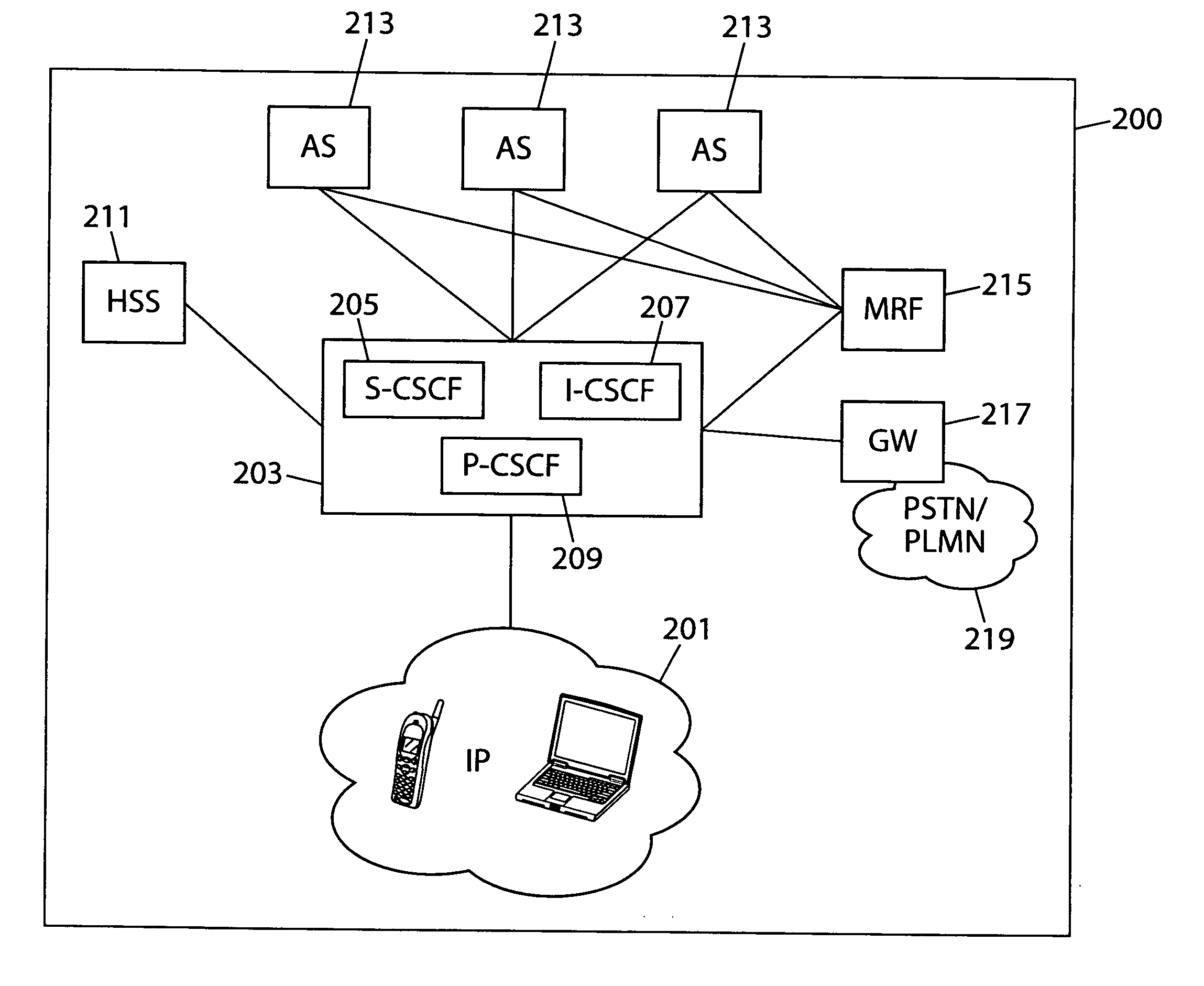
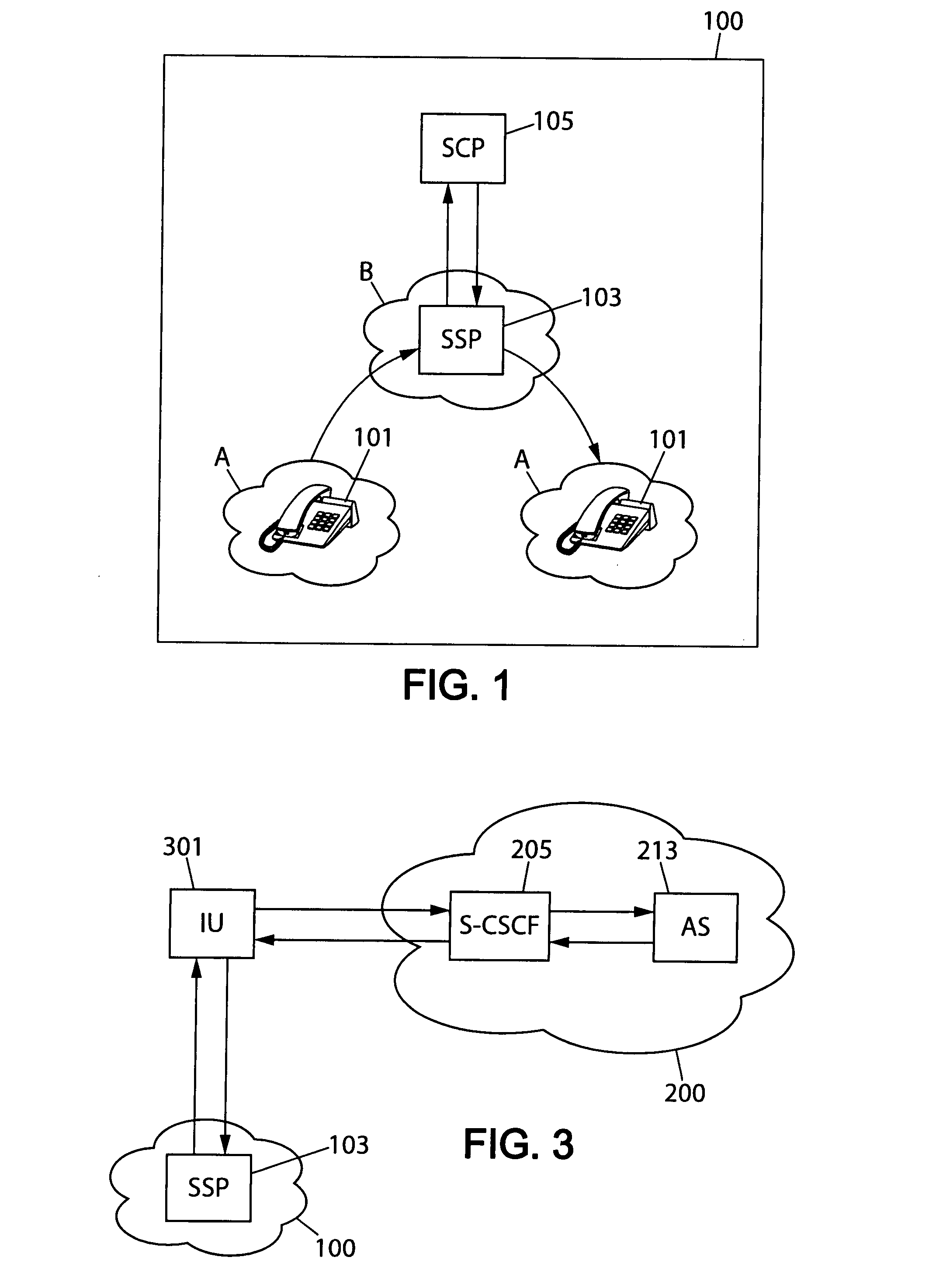
[0027] The invention in accordance with an embodiment of the invention has the advantage that it allows a smooth integration of the IN 100 and the IMS network 200. The invention thus makes it possible to the IMS ASs 213 to control the IN 100 endpoints. Furthermore, there is no need to design the applications separately to the INs 100 and to the IMS networks 200, nor is there a need to implement the IN call model in IMS ASs 213 and develop the applications in IN mode only.

Problems solved by technology

Network service providers are facing a major migration challenge, as the telephony networks currently deployed using TDM digital switches need to be redesigned to use voice over internet protocol (VoIP).
In conventional telephone networks employing TDM, a major issue faced by complex telecom services is the so-called “tromboning”, which means that a switch which implements a specific service and which is used to set up a call also processes the voice bearer channels when the call has already been set up.
In a large network, a call from a user located in a city A to another user also in the city A may need to be processed by a centralized switch located in a city B. If the distance between these two cities is large, then the voice path is long enough to introduce perceptible delays, echoes, and require additional and expensive echo cancellers.
The widely used signaling system #7 (SS7) does not solve the problem even if the transport networks are separate for signaling and voice bearers.
It is not feasible to build centralized service switches processing only SS7 ISUP without also implementing a TDM switching matrix for the voice bearers.
Therefore, TDM centralized service switches continue to cause tromboning issues even in TDM networks using SS7 signaling.
The distance between A, B and C can be hundreds or even thousands of kilometers creating a potential tromboning problem, and possibly inducing echo.
For this reason the SSP 103 is often collocated with local telephone exchanges requiring many points of presence for such SSP function and inducing substantial costs.
However, this induces even higher costs as the SSP function needs to be distributed because of tromboning issues and therefore, in this case also the application needs to be deployed over multiple Points of Presence (POPs).
The tromboning problem no longer exists in a properly designed VoIP network.
In TDM INs 100 most services, e.g. a short numbering plan for a corporation, are lost when roaming outside of the home network, because routing outgoing calls to the home network would create a tromboning problem, and because INAP links are not so frequently allowed among roaming networks.
However, such a migration takes a long time, and for a long time TDM networks such as mobile GSM networks and IMS networks 200 will have to coexist.
However, most IMS devices will have to work in dual mode initially, and therefore the same application logic needs to be available while working in IMS mode or working in TDM mode.
Although this approach does have the merit of allowing a single application to run over a TDM or a VoIP network, it does have significant drawbacks.
It proposes to continue using the standardized call model of the IN 100, and therefore has some limitations.
All applications cannot be developed using the IN call models.
It does not enable building applications controlling both TDM and IP legs in a transparent manner: applications need to control separately TDM to TDM calls, and IP to IP calls.

Method used


Image

  • Network interoperability
  • Network interoperability
  • Network interoperability

Examples


Embodiment Construction

[0035] Next some embodiments of the invention will be described in more detail with reference to FIGS. 3 and 4. In the following description the originating side is the side and corresponding network elements from where the call originates as opposed to terminating side which is the side and corresponding network elements where the call terminates. Furthermore, in the following description, the TDM IN 100 operates in accordance with global system for mobile communications customized applications for mobile network enhanced logic (GSM CAMEL) standard, but the IN 100 could equally use any other TDM communication standard.

[0036]FIG. 3 represents how the IN 100 shown in FIG. 1 and the IMS network of FIG. 2 can be connected to each other via an interface unit (IU) 301. The session initialization protocol (SIP) used by IMS ASs 213 has been extended by the ETSI 3GPP in order to introduce facilities not present in the original Internet Engineering Task Force (IETF) SIP protocol, in particu...


PUM


Abstract

The present invention relates to a method in a communication network for connecting at least one application server (AS) (213) of an internet protocol multimedia subsystem (IMS) (200) to an intelligent network (IN) (100) through an interface unit (301). The IMS (200) comprises a call server control function (CSCF) unit (205) connected to the at least one AS (213) arranged for processing call signaling. In the method the interface unit (301) directs the call signaling to the at least one AS (213) through the CSCF unit (205) and the at least one AS (213) processes the call signaling and sends the processed call signaling through the CSCF unit (205) back to the interface unit (301). Based on the information received in the call signaling processed by the at least one AS (213), the interface unit (301) then directs the call to a destination.

Description

[0001] This application claims priority from the European patent application EP06291323 filed on 17 Aug. 2006, which is hereby incorporated by reference in its entirety. FIELD OF THE INVENTION [0002] The present invention relates to interoperability between communication networks. More specifically, it relates to a situation in which application servers of an internet protocol multimedia subsystem (IMS) provide services to terminals of a time division multiplexing (TDM) intelligent network (IN). BACKGROUND OF THE INVENTION [0003] Network service providers are facing a major migration challenge, as the telephony networks currently deployed using TDM digital switches need to be redesigned to use voice over internet protocol (VoIP). Emerging standards such as the European Telecommunication Standards Institute (ETSI) 3rd Generation Partnership (3GPP) IMS also change the way network services may be designed. [0004] In conventional telephone networks employing TDM, a major issue faced by ...

Claims


Application Information

Patent Timeline
IPC IPC(8): H04L12/56
CPCH04M7/1205H04Q3/0045H04L65/103H04L65/104H04L65/1016
Inventor HERSENT, OLIVIER
Owner COMVERSE
Why Eureka
Eureka Blog
Learn More