Microphone package

a technology for microphones and packages, applied in the direction of microphone structural association, piezoelectric/electrostrictive transducers, transducer types, etc., can solve the problems of increasing the overall size of the microphone package, and it is difficult to downsize the microphone package in the conventionally-known technology, so as to prevent the incident light from reaching the sound hole, reduce the distance between the microphone chip and the sound hole, and prevent the effect of liquid die-bonding material

Inactive Publication Date: 2008-03-06
YAMAHA CORP
View PDF2 Cites 9 Cited by
  • Summary
  • Abstract
  • Description
  • Claims
  • Application Information

AI Technical Summary

Benefits of technology

[0010] In the manufacturing of the microphone package, a liquid die-bonding material is applied to the prescribed position for mounting the microphone chip on the mounting surface, wherein it is possible to prevent the liquid die-bonding material from flowing over the mounting surface by means of the projection wall. Therefore, even when the distance between the microphone chip and the sound hole is reduced, it is possible to prevent the liquid die-bonding material from flowing into the sound hole. In addition, the projection wall blocks the light incident into the sound hole; hence, it is possible to easily prevent the incident light from reaching the microphone chip composed of silicon.
[0011] In the above, the sound hole is surrounded by the projection wall, by which it is possible to reliably prevent the liquid die-bonding material from unexpectedly flowing into the sound hole.
[0012] In addition, the prescribed portion of an external connection wire is electrically connected to the microphone chip and is exposed on the upper surface of the projection wall. This makes it possible to prevent the liquid die-bonding material from covering the prescribed portion of the external connection wire when the microphone chip is fixed onto the mounting surface; thereafter, it is possible to easily establish an electrical connection between the microp...

Problems solved by technology

However, this increases the overall size of the microphone package; hence, it is v...

Method used


Image

  • Microphone package
  • Microphone package
  • Microphone package

Examples


Embodiment Construction

[0025] The present invention will be described in further detail by way of examples with reference to the accompanying drawings.

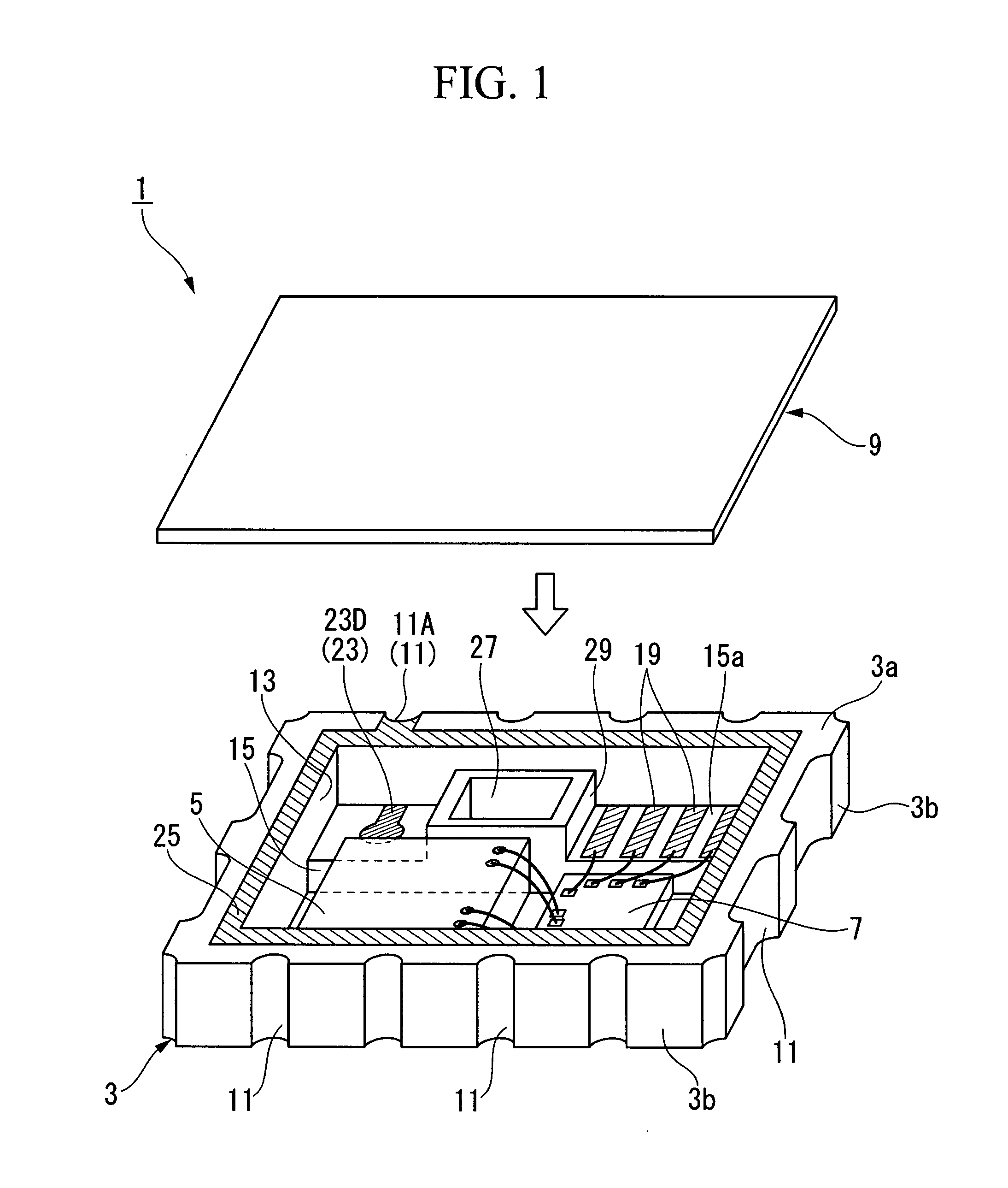
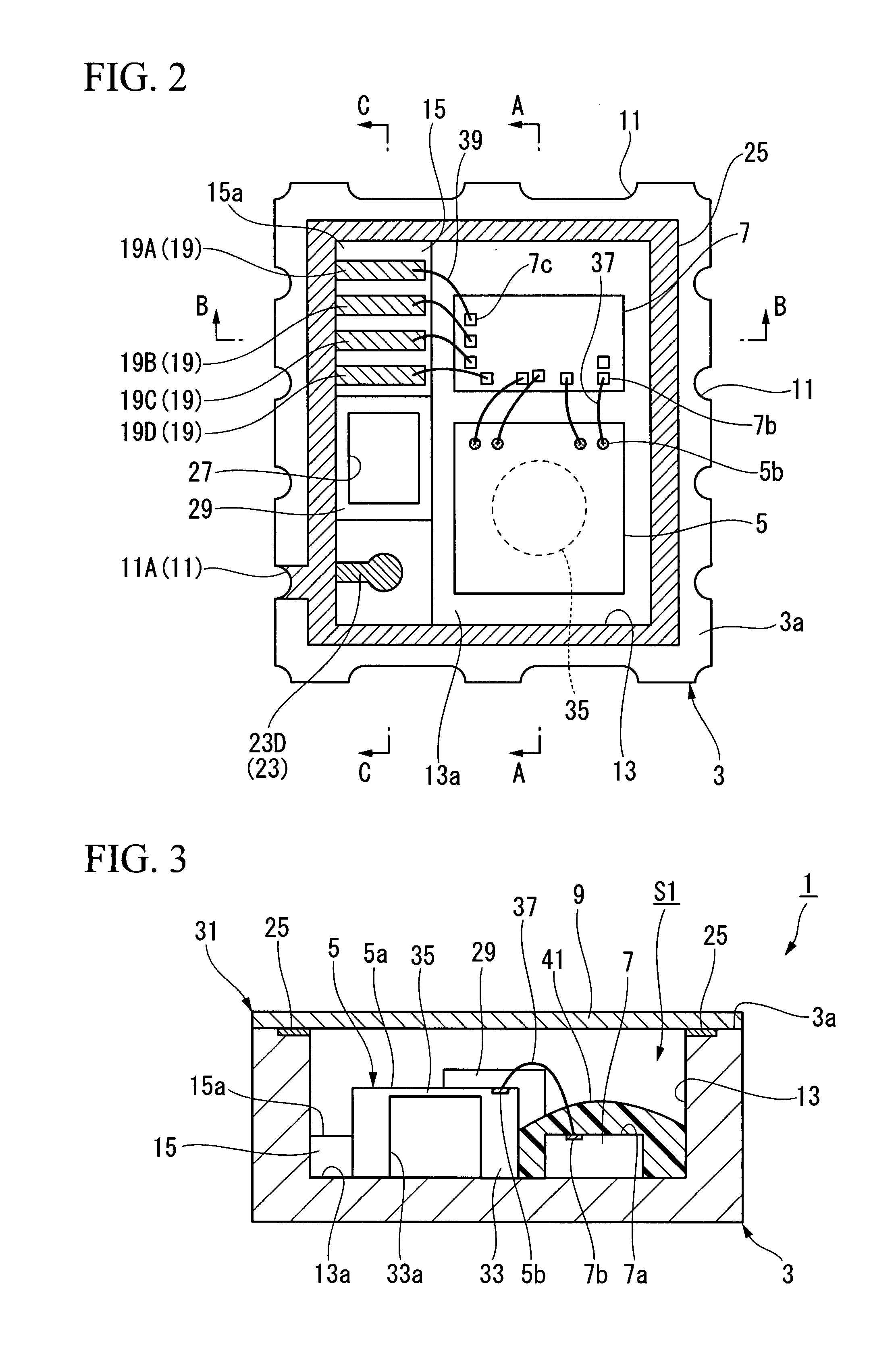
[0026] A microphone package 1 according to a preferred embodiment of the present invention will be described with reference to FIGS. 1 to 5. The microphone package 1 is constituted of a substrate 3, a microphone chip 5 arranged in connection with a surface 3a of the substrate 3, an LSI chip 7, and a cover board 9.

[0027] The substrate 3 is shaped like a plate having a rectangular shape in plan view, in which a plurality of recesses 11 are formed on a side wall 3b and are each opened in both of the surface 3a and a backside 3c. A hollow portion 13, which is recessed downwardly from the surface 3a, is formed in the substrate 3.

[0028] The microphone chip 5 and the LSI chip 7 are arranged on a bottom 13a (i.e., a mounting surface) of the hollow portion 13. As shown in FIGS. 1 to 4, a step portion 15 (or a wall) is formed and elongated along one side of the al...


PUM


Abstract

A microphone package includes a housing, which has a cavity and a sound hole for allowing the cavity to communicate with the exterior, and a microphone chip, which is mounted on the mounting surface so as to detect sound within the cavity. The sound hole is opened in connection with the mounting surface and is surrounded by a projection wall projecting upwardly from the mounting surface at a prescribed position in proximity to the microphone chip.

Description

BACKGROUND OF THE INVENTION [0001] 1. Field of the Invention [0002] The present invention relates to microphone packages encapsulating microphones such as silicon condenser microphones. [0003] This application claims priority on Japanese Patent Application No. 2006-241792, the content of which is incorporated herein by reference. [0004] 2. Description of the Related Art [0005] Japanese Patent Application Publication No. 2004-537182 teaches an example of a microphone package, in which a miniature silicon condenser microphone is encapsulated in a housing having a cavity and a sound hole communicating with the exterior, wherein a microphone chip (for detecting sound) and an LSI chip (for controlling the microphone chip) are mounted on the mounting surface of the housing by use of a die-bonding material. This type of microphone package can be redesigned such that the LSI chip is sealed with a resin (or a potting material), by which the LSI chip is protected In addition, it can be redesi...

Claims


Application Information

Patent Timeline
IPC IPC(8): H04R19/04
CPCH04R19/04H04R1/04H04R19/016H04R31/006
Inventor SAKAKIBARA, SHINGOSAITOH, HIROSHI
Owner YAMAHA CORP
Why Eureka
Try Eureka