Compressor bearing

Active Publication Date: 2008-03-06
KOBE STEEL LTD
View PDF15 Cites 20 Cited by
  • Summary
  • Abstract
  • Description
  • Claims
  • Application Information

AI Technical Summary

Benefits of technology

[0007]It is an object of the present invention to provide a compressor bearing with reduc

Problems solved by technology

Consequently, there has been a case where the bearing cannot withstand and is damaged.
If the angle of the oil groove 23 is set small, the area of oil pressure acting on the rotor shaft 21 becomes smaller a

Method used


Image

  • Compressor bearing
  • Compressor bearing
  • Compressor bearing

Examples


Embodiment Construction

[0027]Embodiments of the present invention will be described hereinunder with reference to the drawings.

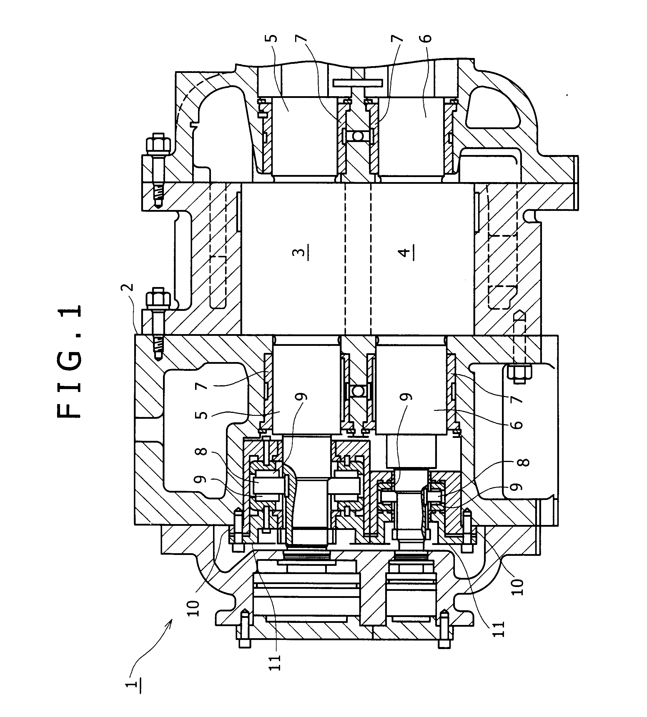
[0028]FIG. 1 shows an oil-cooled screw compressor 1 using a bearing embodying the present invention. A pair of intermeshing male and female screw rotors 3, 4 is accommodated within a casing 2 of the oil-cooled screw compressor 1. Rotor shafts 5 and 6 at both ends of the screw rotors 3 and 4 respectively are supported by radial bearings 7 embodying the present invention which bearings will be described later. Outside the left-hand radial bearings 7 in FIG. 1 there are disposed thrust bearings 9 through bearing caps 10 and 11. The thrust bearings 9 support disc-like thrust members 8 from both sides. The thrust members 8 are fitted on the rotor shafts 5 and 6. The right-hand rotor shaft 5 in FIG. 1 of one screw rotor 3 is driven for rotation by a motor (not shown) and the other screw rotor 4 rotates along with rotation of the screw rotor 3.

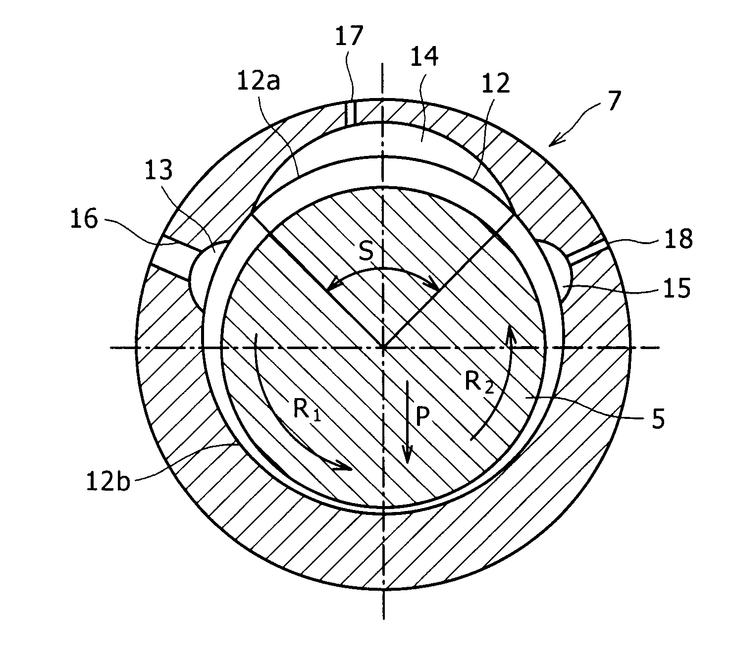
[0029]FIG. 2 is an enlarged sectional view o...


PUM


Abstract

In a compressor bearing for supporting a rotor shaft of a compressor, a first oil groove is formed in a bearing surface on the side opposite to a bearing load acting direction, a second oil groove is formed in a position adjacent to the first oil groove in an anti-rotational direction, a first oil channel and a second oil channel communicating with the first oil groove and the second oil groove, respectively, to supply oil to the first and second oil grooves from an exterior, common oil supply source are provided, a circumferential length of the second oil groove is set larger than that of the first oil groove, and a minimum value of a sectional area perpendicular to the longitudinal direction of the second oil channel is set smaller than that of a sectional area perpendicular to the longitudinal direction of the first oil channel. The compressor bearing of such a configuration is small in load induced by oil pressure and exhibits an outstanding rotor shaft cooling effect.

Description

BACKGROUND OF THE INVENTION[0001]1. Field of the Invention[0002]The present invention relates to a compressor bearing, e.g., a bearing for a screw compressor.[0003]2. Description of the Prior Art[0004]Heretofore, as a radial plain bearing for supporting a rotor shaft of a screw compressor, as is disclosed in Japanese Patent Laid-Open Publication No. 2005-69186, there has been used a dynamic pressure plain bearing having a fixed sliding surface, especially a cylindrical full journal bearing, because a high load is imposed on the bearing in a certain constant direction during operation of the compressor. In the full journal bearing, as shown in FIG. 8, in order to supply oil to a bearing surface 22 which supports a rotor shaft 21, an oil groove 23 is formed on the side opposite to the direction of a bearing load P and oil is supplied from the exterior to the oil groove 23 through an oil supply hole 24. Since the oil groove 23 is used also for cooling the rotor shaft 21, a circumferent...

Claims


Application Information

Patent Timeline
IPC IPC(8): F16C33/66
CPCF01C21/02F16C33/1075F04C2240/52F04C18/16F16C17/028F16C2360/43F04C29/02F16C33/10F16C37/00
Inventor YOSHIMURA, SHOJIAMANO, YASUSHI
Owner KOBE STEEL LTD
Why Eureka
Try Eureka