Method for production of stacked battery

a technology of stacked batteries and stacked plates, which is applied in the direction of cell components, final product manufacturing, sustainable manufacturing/processing, etc., can solve the problems of high probability of cutting and breaking of endmost current collection tabs in welding process, high welding strength, and high probability of cutting and breaking of endmost current collection tabs. , to achieve the effect of increasing the number of current collection tabs and stably welding

Active Publication Date: 2008-03-13
ENVISION AESC ENERGY DEVICES LTD
View PDF0 Cites 243 Cited by
  • Summary
  • Abstract
  • Description
  • Claims
  • Application Information

AI Technical Summary

Benefits of technology

[0022]Thus, with a method for production of a stacked battery in the third aspect of the invention, each group of positive electrode current collection tabs or negative electrode current collection tabs are formed by stacking a number of current collection tabs less than the predetermined number for stacking and positive electrode current collection tabs or negative electrode current collection tabs are not taken out consecutively from positive electrodes or negative electrodes, whichever appropriate, and laid one on the other in the stacked member but every other or every plural number of current collection tab is taken out to form a group. Then, the positions of the groups of current collection tabs are displaced from each other. With this arrangement, it is possible to make the positive electrode lead terminal and the negative electrode lead terminal less liable to incline relative to the stacked member.
[0031]When the battery is used in an application where it is not necessary to flow a large electric current, is possible to improve the reliability of the sealed section by reducing the length of the projection of the thermally welded section of the flexible film casing of the lead terminal. Additionally, the profile of the lead terminal can be made T-shaped, L-shaped or transversally asymmetrical in terms of the length from the center to the transversal edge of the lead terminal depending on the position where the lead terminal is drawn out from the flexible film casing.
[0034]Thus, according to the present invention, it is now possible to stably weld and connect positive electrode current collection tabs and negative electrode current collection tabs respectively to a positive electrode lead terminal and a negative electrode lead terminal regardless of the number of positive electrode current collection tabs and the number of negative electrode current collection tabs so that it is possible to increase the number of current collection tabs that are laid one on the other in a stacked battery without damaging the current collection tabs and the reliability of the stacked battery.

Problems solved by technology

In other words, there arises a problem that current collection tabs are apt to be cut and broken when a large number of tabs are welded collectively.
Additionally, the strength for withstanding welding such as ultrasonic welding of a current collection tab whose thickness is as small as several micrometers to tens of several micrometers is obviously limited and hence there arises a problem that particularly the endmost current collection tab can highly probably be cut and broken in a welding process when the number of current collection tabs becomes large.

Method used


Image

  • Method for production of stacked battery
  • Method for production of stacked battery
  • Method for production of stacked battery

Examples


first embodiment

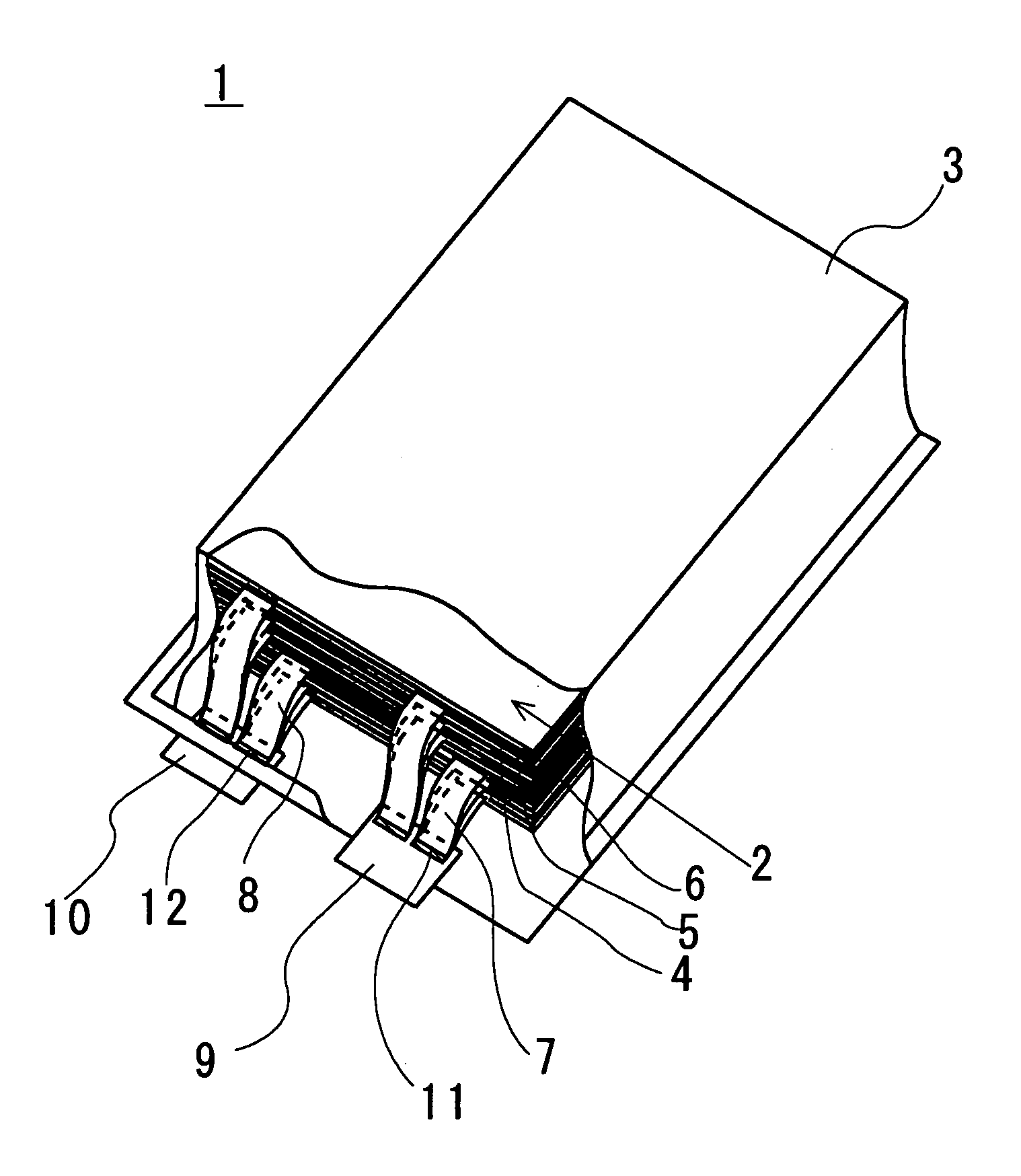
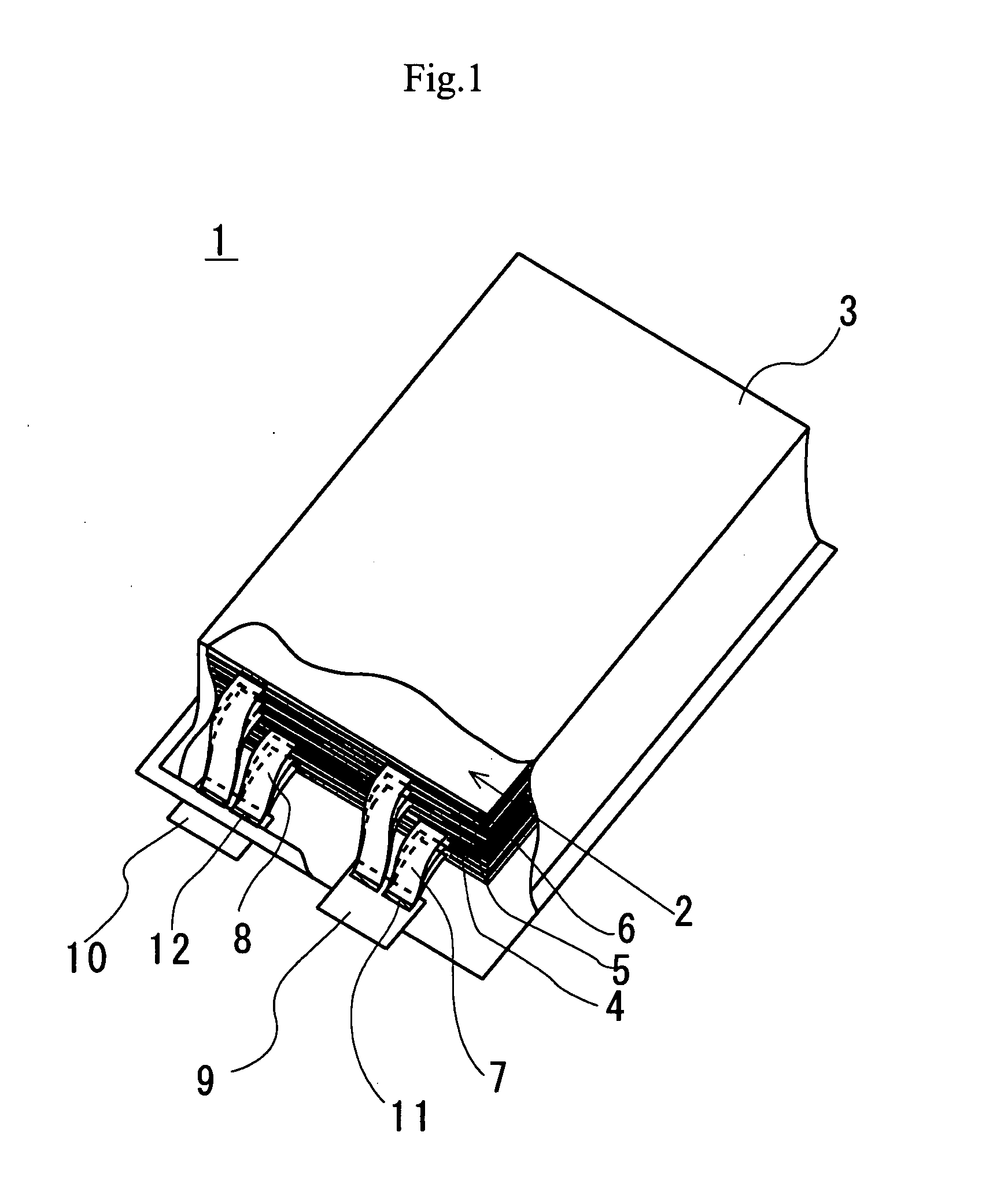
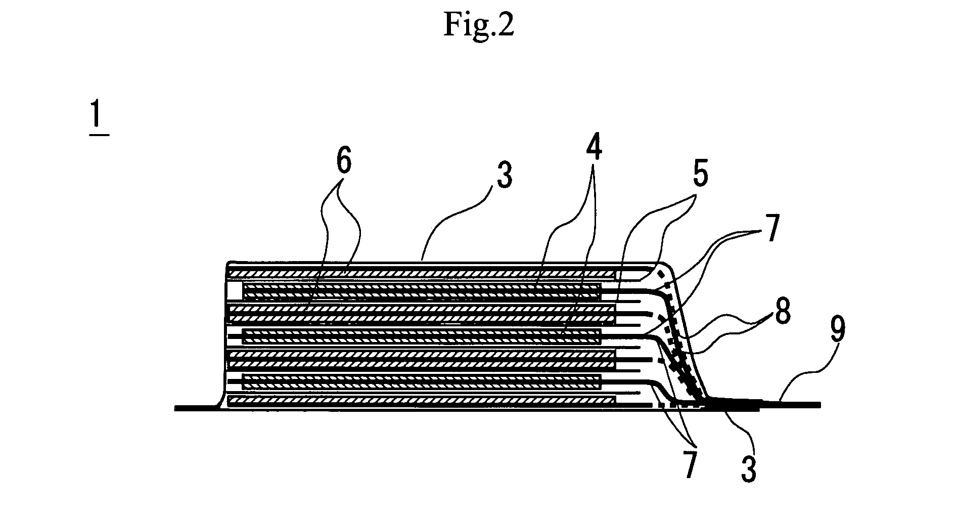
[0050]FIG. 1 is a partly cut out schematic perspective view of a stacked battery according to the present invention. The stacked member of the stacked battery is illustrated in detail in FIG. 3B.

[0051]The stacked battery 1 is formed by covering the stacked member 2 formed by laying positive electrodes 4 and negative electrodes one on the other with separators 5 interposed between them with a flexible film casing 3. In the stacked battery 1, the positive electrode current collection tabs 7 that are bonded to the positive electrodes 4 are connected to the positive electrode lead terminal 9 at the junction 11.

[0052]Similarly, the negative electrode current collection tabs 8 that are bonded to the negative electrodes 6 are connected to the welding section 12 of the negative electrode lead terminal 10 and thermally welded to and sealed by the flexible film casing 3.

[0053]In the following description, it is assumed that a stacked battery according to the invention is a stacked lithium-ion...

second embodiment

[0064]FIG. 4 is a schematic perspective view of part of a stacked battery according to the present invention after welding the positive electrode current collection tabs and the positive electrode lead terminals.

[0065]When positive electrodes 4 and negative electrode 6 are laid one on the other with separators 5 interposed between them to form a stacked member 2, the positive electrode current collection tabs are arranged in such a way that the positive electrode current collection tabs 7 can be divided into first group of positive electrode current collection tabs 7A, second group of positive electrode current collection tabs 7B and third group of positive electrode current collection tabs 7C and any two adjacently located two groups can be separated from each other by a gap in a direction orthogonal relative to the direction in which the positive electrode current collection tabs 7 are taken out.

[0066]Then, the first group of positive electrode current collection tabs 7A, the seco...

third embodiment

[0068]FIG. 5 is a schematic perspective view of part of a stacked battery according to the present invention after welding the current collection tabs and the lead terminals.

[0069]The positive electrode current collection tabs are divided into groups in the direction in which the positive electrodes of the stacked member are laid in the first embodiment.

[0070]On the other hand, in the third embodiment, every other positive electrode current collection tab is, in other words the second, the fourth and the sixth positive electrode current collection tabs 7 are, taken and laid one on the other to form the first group of positive electrode current collection tabs 7A. Similarly, the first, the third and the fifth positive electrode current collection tabs 7 are taken and laid one on the other to form the second group of positive electrode current collection tabs 7B.

[0071]The positions for drawing out the positive electrode current collection tabs 7 are not lopsided and uniformly distribu...


PUM

PropertyMeasurementUnit
currentaaaaaaaaaa
currentaaaaaaaaaa
currentaaaaaaaaaa

Abstract

A method for production of a stacked battery having a plurality of positive electrode current collection tabs and a plurality of negative electrode current collection tabs drawn out from a stacked member formed by laying positive electrodes and negative electrodes alternately one on the other with separators interposed between them and bonded respectively to a positive lead terminal and a negative lead terminal comprises a step of determining in advance a simultaneously bondable number, or the number of positive electrode current collection tabs and the number of negative electrode current collection tabs that can be laid one on the other and collectively bonded, and bonding conditions for bonding them and a step of forming groups of current collection tabs, each group being formed by laying a number of current collection tabs not exceeding the simultaneously bondable number one on the other, displacing the bonding positions of the groups of positive electrode current collection tabs or those of negative electrode current collection tabs relative to each other in the direction of drawing out the positive electrode current collection tabs or the negative electrode current collection tabs, whichever appropriate, or in a direction perpendicular to the direction on the surface of the positive lead terminal or the negative lead terminal, whichever appropriate, and collectively bonding the positive electrode current collection tabs or the negative electrode current collection tabs of each group under the bonding conditions.

Description

CROSS-REFERENCE TO RELATED APPLICATIONS[0001]This application is based upon and claims the benefit of priority from prior Japanese Patent Application No. 2006-243827, filed Sep. 8, 2006, the entire contents of which are incorporated herein by reference.BACKGROUND[0002]1. Technical Field[0003]This invention relates to a method for production of a stacked battery. More particularly, the present invention relates to a method for production of a stacked battery that is suitable for production of a stacked lithium-ion battery where a plurality of current collection tabs of positive electrodes and negative electrodes are connected in parallel.[0004]2. Related Art[0005]Lithium ion batteries have been and being used in portable appliances such as portable telephones and digital cameras to meet the demand for downsized high capacity power sources. Additionally, lithium ion batteries are being used as high energy density power sources having no memory effect for electric bicycles and electric...

Claims


Application Information

Patent Timeline
Patent Type & Authority Applications(United States)
IPC IPC(8): H01M10/38H01M10/05H01M10/0585H01M50/54H01M50/55H01M50/557H01M50/566
CPCH01M2/021H01M2/0212H01M2/266H01M2/30Y10T29/49108H01M10/0436H01M10/0525H01M10/0585Y02E60/122H01M10/0413Y02E60/10H01M50/557H01M50/54Y02P70/50H01M50/55H01M50/566H01M10/38
Inventor DAIDOJI, TAKAOKUMEUCHI, TOMOKAZUZAMA, KOICHI
Owner ENVISION AESC ENERGY DEVICES LTD
Why Eureka
Try Eureka