Simulated neon illuminating sign

a neon and illuminating technology, applied in the field of signs, to achieve the effect of cheap cost and simple structur

Inactive Publication Date: 2008-03-13
CHIANG JOHN +1
View PDF7 Cites 7 Cited by
  • Summary
  • Abstract
  • Description
  • Claims
  • Application Information

AI Technical Summary

Benefits of technology

[0010]A main object of the present invention is to provide a simulated neon illuminating sign. Such a simulated neon illuminating sign is simple structure, cheap cost, and without employment anything that may be harmful to the environment such as mercury.
[0011]Another object of the present invention is to provide an illumination sign which is capable of producing an illumination effect as that of conventional neon illuminating signs, yet without involving the utilization of any harmful gases or substances to producing illumination.
[0012]Another object of the present invention is to provide an illumination sign which easy to manufacture and simple in structure, wherein the illumination sign could be utilized in a wide variety of circumstances for providing high quality illumination of predetermined sign characters. Moreover, the present invention is capable of utilizing a wide variety of light sources for providing illumination of sign characters.
[0016]a highlighting element provided at the rear side of the sign panel and arranged in such a manner that when the light passes through the protruding portions of the sign panel, the highlighting element creates a neon illuminating effect at the protruding portions of the sign panel, such that the character signs are illuminated at the front displaying side of the sign panel through the protruding portions for simulating a three dimensional neon illumination effect of the sign panel.

Problems solved by technology

Such a simulated neon illuminating sign is simple structure, cheap cost, and without employment anything that may be harmful to the environment such as mercury.

Method used


Image

  • Simulated neon illuminating sign
  • Simulated neon illuminating sign
  • Simulated neon illuminating sign

Examples


Embodiment Construction

[0025]Throughout the following detailed description, the same reference numerals refer to the same elements in all figures.

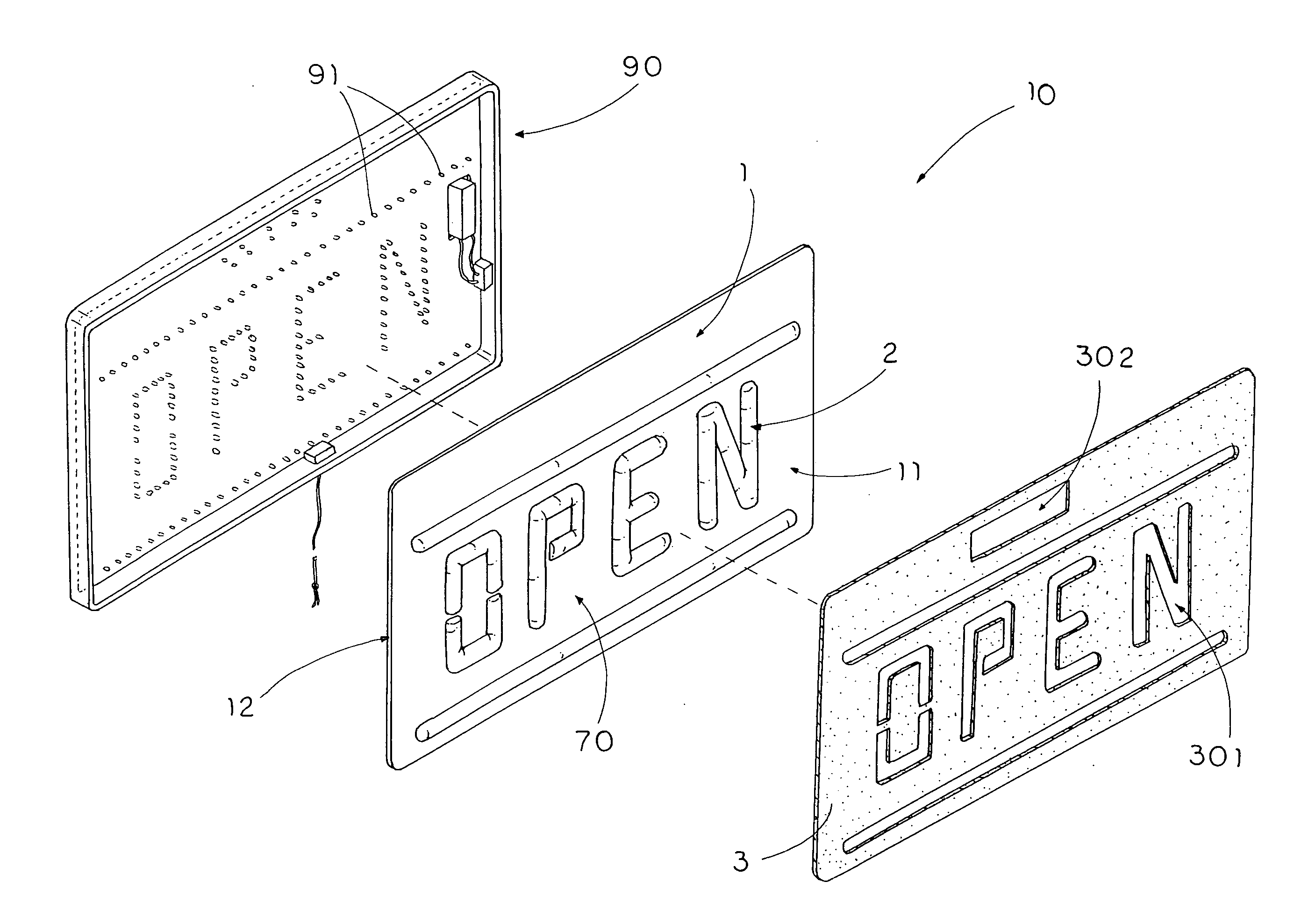
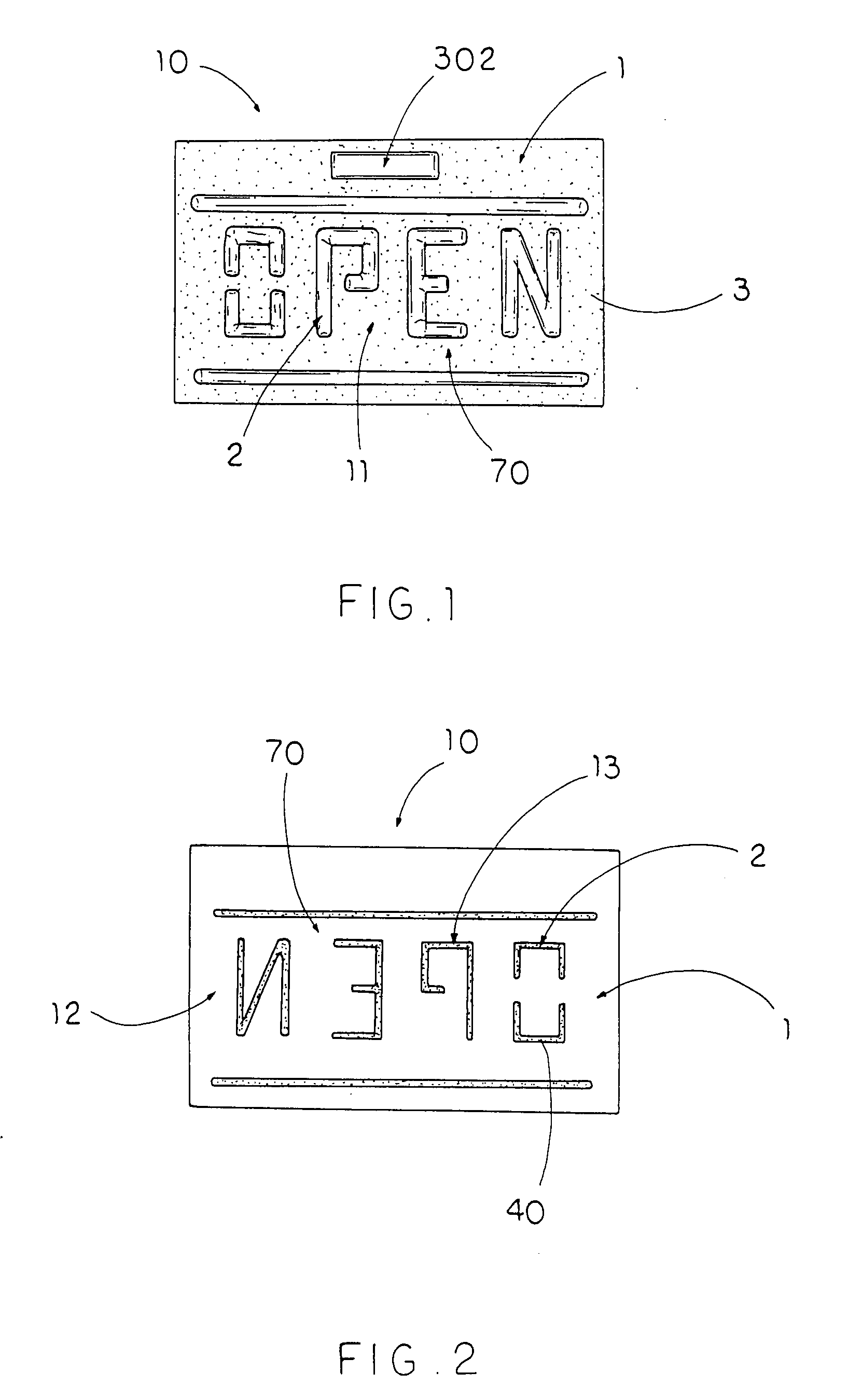
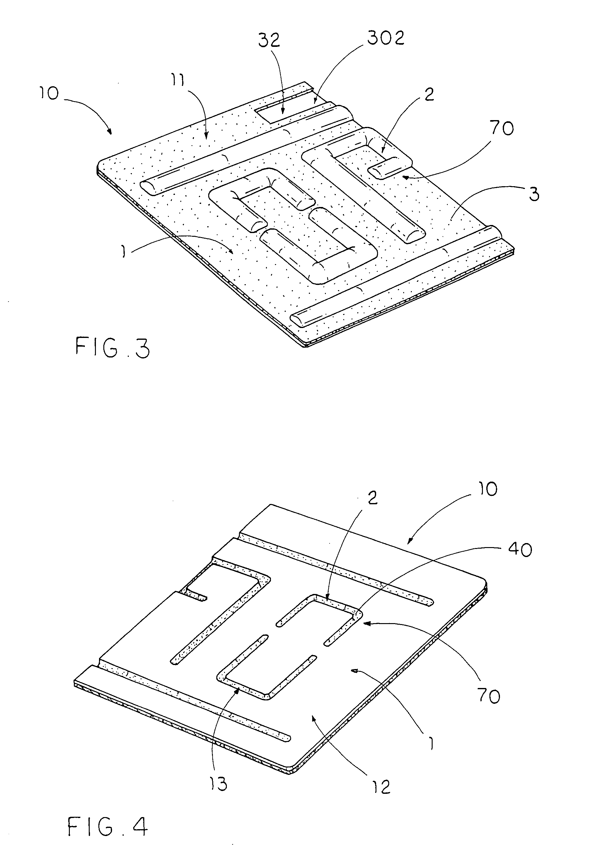
[0026]Referring to FIG. 1 and FIG. 2, the sign panel, made of light transmitting material, has a front displaying side and a rear side, the sign panel 10 has a background portion I that is preferably a flat surface and a protruding portion 2 that forms a sign character, wherein a lighting blocking layer 3 attached to said background portion 2 of the sign panel 10, and a highlight coating 5 coated on said protruding portion 2 of the rear side of the sign panel 10.

[0027]Further more, as shown of FIG. 1 and FIG. 5, the background portion 1 of the front displaying side of the sign panel 10 is coated with a black color blocking layer 3 so that the light can not go though the background portion 1, and the protruding portion 2 of the front displaying side of the sign panel 10 forms the sign character.

[0028]As shown of FIG. 2 and FIG. 5, the background portion 1 of the ...


PUM


Abstract

A sign panel made of light transmitting material, has a front displaying side and a rear side, the sign panel has a background portion that is preferably a flat surface and a protruding portion that forms a sign character, wherein a lighting blocking layer attached to said background portion of the sign panel, and a highlight coating coated on said protruding portion of the rear side of the sign panel. Light can go through the protruding portion with a highlight coating. The sign panel can use without a complicated neon light tubes, and the sign panel contains no mercury versus argon based neon tubes. This is a huge win from the environmental side as there is no use for mercury inside LED signs.

Description

CROSS REFERENCE OF RELATED APPLICATION [0001]This is a non-provisional application of a provision application having an application No. of 60 / 843,459 and a filing date of Sep. 08, 2006.BACKGROUND OF THE PRESENT INVENTION [0002]1. Field of Invention[0003]The present invention relates to a sign, and more particularly to an illumination sign which is capable of simulating a typical neon illuminating sign without involving the difficulties associated therewith.[0004]2. Description of Related Arts[0005]A conventional neon illuminating sign usually uses argon based tubes as a light source. The argon based tubes always has mercury in it. The mercury may be harmful to the environment as well as the user when leakage occurs. As a result, many people may switch to LED illuminating sign instead of the conventional neon illuminating sign. What is we basically have as a light source is a diode with specified crystals attached to produce the intense illumination without employment anything that m...

Claims


Application Information

Patent Timeline
Patent Type & Authority Applications(United States)
IPC IPC(8): G09F13/04G09F13/20
CPCG09F13/22G09F13/04
Inventor CHIANG, JOHNCHIANG, KEN-SHENG
Owner CHIANG JOHN
Why Eureka
Try Eureka