Emissions reduction system

a technology of emission reduction system and exhaust system, which is applied in the direction of machines/engines, mechanical equipment, separation processes, etc., can solve the problems of increased nox, unburned hydrocarbon and soot emissions, and engine manufacturers having difficulty in designing engines that meet all the regulations

Inactive Publication Date: 2008-03-13
CATERPILLAR INC
View PDF7 Cites 123 Cited by
  • Summary
  • Abstract
  • Description
  • Claims
  • Application Information

AI Technical Summary

Problems solved by technology

In meeting these regulations, engine manufacturers are challenged with designing engines that both meet stringent exhaust regulations as well as provide fuel-efficient power conversion.
Additionally, engine manufacturers have difficulty in designing engines that meet all of the regulations for the several different types of exhaust pollutants.
If excess oxygen is present, the local mixture is

Method used


Image

  • Emissions reduction system
  • Emissions reduction system
  • Emissions reduction system

Examples


Embodiment Construction

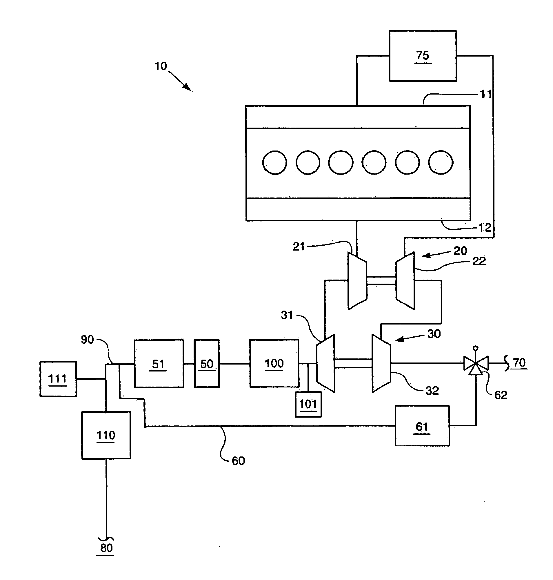
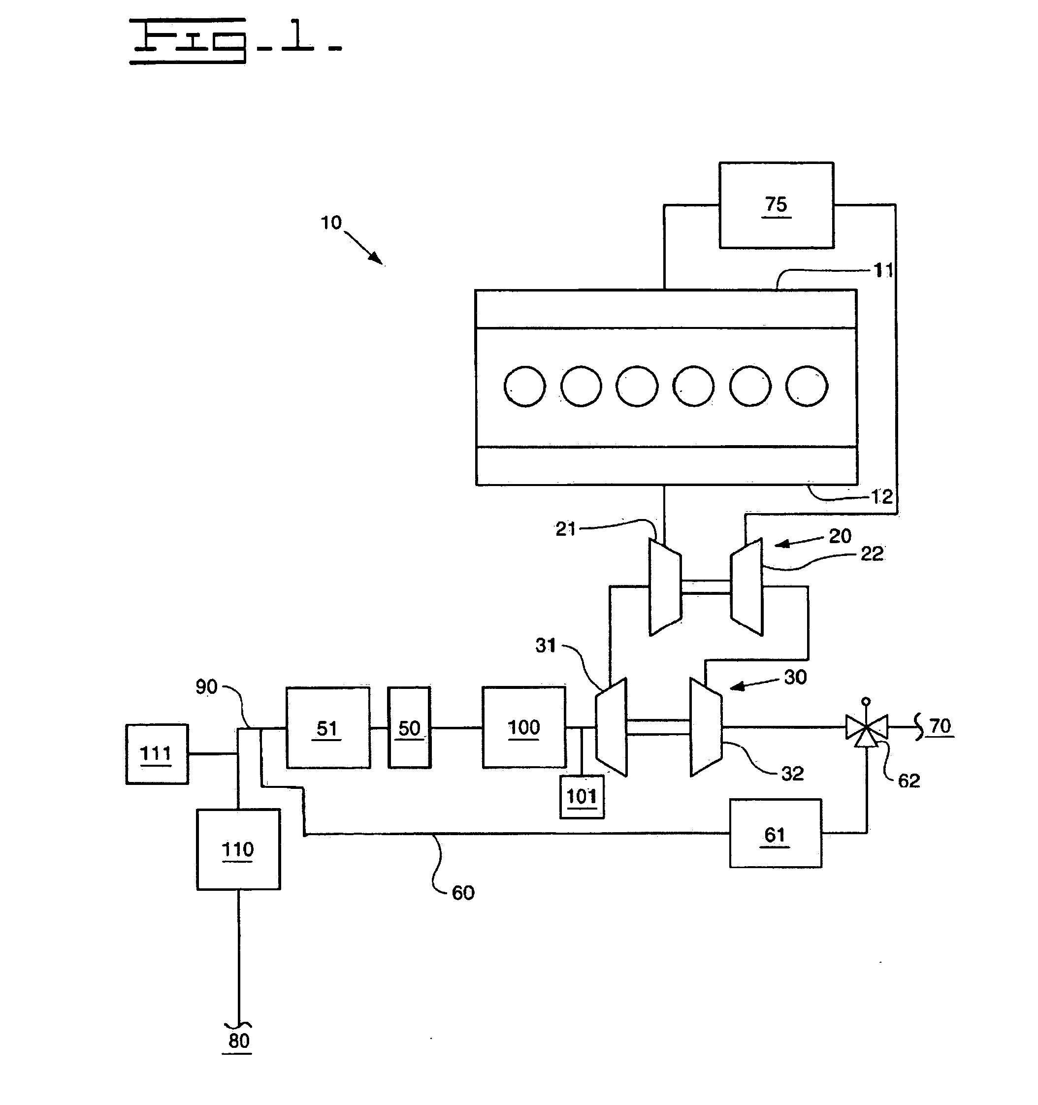
[0017]FIG. 1 illustrates an engine 10 according to an exemplary embodiment of the present disclosure. Although FIG. 1 depicts an engine 10, the reader should appreciate that the disclosed system for treating exhaust gas will apply to any exhaust stream where unwanted NOx or particulate matters are present. For example, any fossil-fuel burning power plant may also benefit from the disclosed system.

[0018]In this particular embodiment, engine 10 has intake manifold 11 and exhaust manifold 12. Intake air enters intake manifold 11 to facilitate the combustion within engine 10. Exhaust gas from the combustion process then exits via exhaust manifold 12.

[0019]The oftentimes high-temperature and high-pressure exhaust may then be used to drive a high-pressure turbocharger 20. In this case, exhaust gas drives turbine 21 to impart rotational energy to compressor wheel 22. Compressor wheel 22 is connected to turbine 21 via a common shaft. As the high-pressure exhaust drives turbine 21, the rotat...


PUM

PropertyMeasurementUnit
Temperatureaaaaaaaaaa
Pressureaaaaaaaaaa

Abstract

An engine, an exhaust system, and a method for reducing NOx in an exhaust stream are provided. The system comprises a first SCR catalyst, a second SCR catalyst, and a particulate filter positioned between the first and second SCR catalyst. The engine comprises an intake air system, at least one combustion chamber, and an exhaust system comprising a first SCR catalyst positioned upstream of a particulate filter and a second SCR catalyst positioned downstream of the particulate filter. The method comprises the steps of passing the exhaust through a low-temperature SCR catalyst, passing the exhaust through a particulate filter, and passing the exhaust through a high-temperature SCR catalyst.

Description

TECHNICAL FIELD [0001]The present disclosure relates generally to a system and method for reducing pollutants in an exhaust system and, more particularly, to a system for reducing nitrogen oxides (“NOx”) within the exhaust stream of an engine.BACKGROUND [0002]Fuel-burning power plants, such as some furnaces and internal and external combustion engines, may emit pollutants such as carbon monoxides, NOx, particulate matters, and sulfur oxides, to name a few.[0003]Many of these pollutants are regulated by governmental agencies, which mandate that engines-along with other fuel-burning plants-not exceed certain maximum limitations. In meeting these regulations, engine manufacturers are challenged with designing engines that both meet stringent exhaust regulations as well as provide fuel-efficient power conversion. Additionally, engine manufacturers have difficulty in designing engines that meet all of the regulations for the several different types of exhaust pollutants.[0004]For diesel ...

Claims


Application Information

Patent Timeline
IPC IPC(8): F01N5/04F01N3/00F01N3/10F02B33/44
CPCB01D53/9431B01D53/9477B01D2255/20723B01D2255/50B01D2258/012F01N13/0093F01N3/206F01N2250/02F02B37/013Y02T10/24F01N13/009F01N3/035Y02T10/12
Inventor ROBEL, WADE J.DRISCOLL, JAMES J.
Owner CATERPILLAR INC
Why Eureka
Try Eureka