
Eureka
For R&D, Eureka makes reading and utilizing patents & technical documents easy.
Eureka AIR
Designed for self-driven R&D workflows. Generate viable solutions, solve complex R&D challenges, empower your innovation with AI.

Eureka Materials
Designed for material experts only. Revolutionize your material R&D, from search, analyze, to developing new materials.

TechResearch
Generate reliable direction feasibility study reports for your R&D in just a few steps.

TechSeek
Discover and master advanced knowledge NOW. Basics, ideas, possibilities, all at once.

TechMind
As an expert in R&D Theories, TechMind can generates customized viable solutions instantly.

TechRisk
Analyze your overall solution with one click, know your potential R&D risks in advance.

TechMonitor
Get weekly tech updates, stay abreast of the latest tech innovations and key insights.
Pressure sensor with diaphragm for detecting pressure
- Summary
- Abstract
- Description
- Claims
- Application Information
AI Technical Summary
Benefits of technology
Problems solved by technology
Method used
Image

Examples
embodiment 1
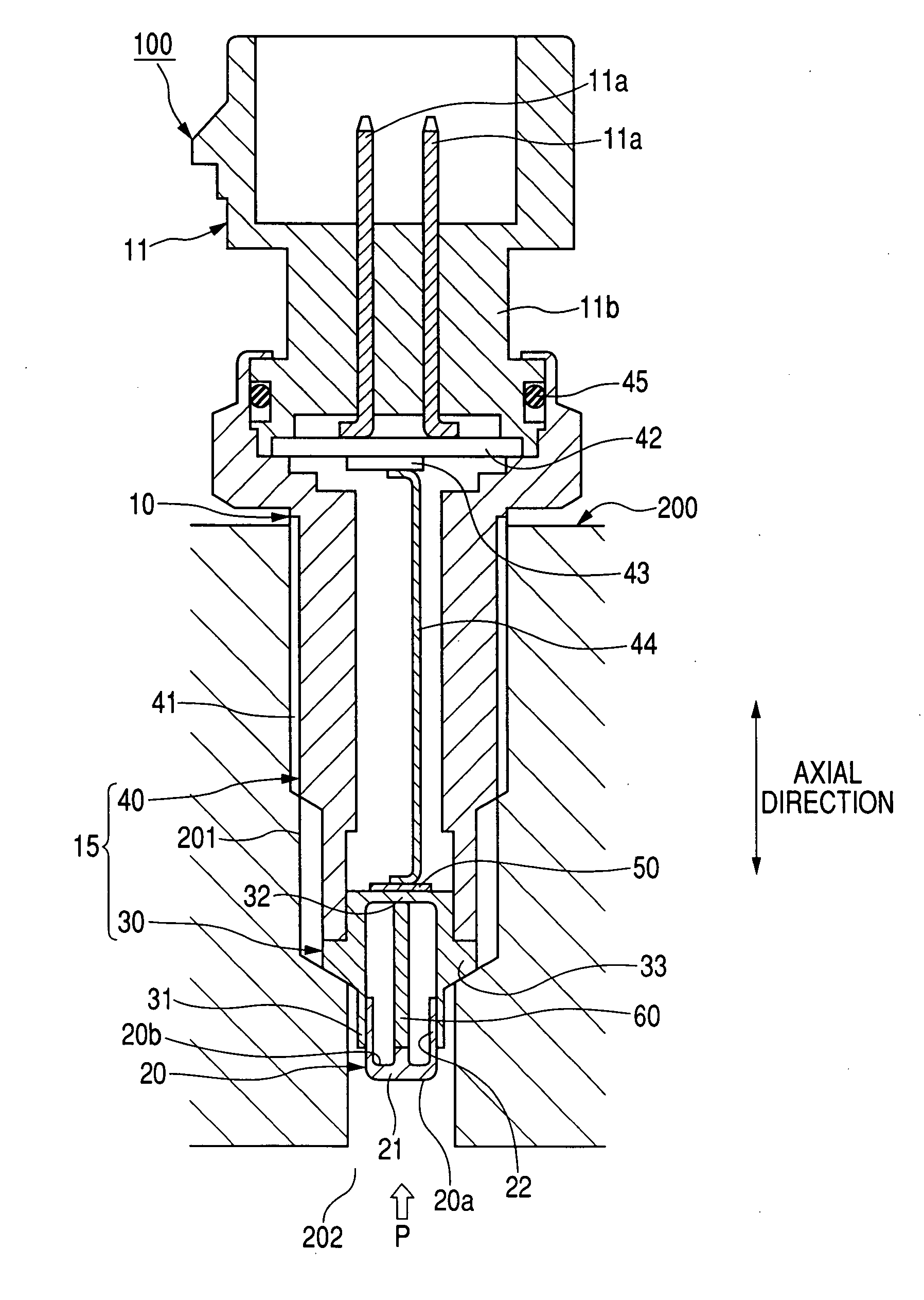
[0022]FIG. 1 is a sectional view schematically showing a pressure sensor according to a first embodiment of the present invention.
[0023]A pressure sensor 100 shown in FIG. 1 is attached to a combustion chamber 202 of an internal combustion engine 200. Therefore, the sensor 100 is applied as a combustion pressure sensor for detecting a combustion pressure P of a combustion gas in the chamber 202. As shown in FIG. 1, the sensor 100 has a cylindrical case portion 10 and a connector portion 11 attached to the case portion 10. In the engine 200, an attaching hole 201 is disposed to extend from an outer surface of the engine 200 to the chamber 202. The case portion 10 is inserted into the hole 201 such that a distal portion of the case portion 10 faces the chamber 202, and a proximal portion of the case portion 10 closes the hole 201 on the outer surface of the engine 200.
[0024]The case portion 10 has a base portion 15 and a pressure receiving diaphragm 20 attached to the base portion 15 ...
embodiment 2
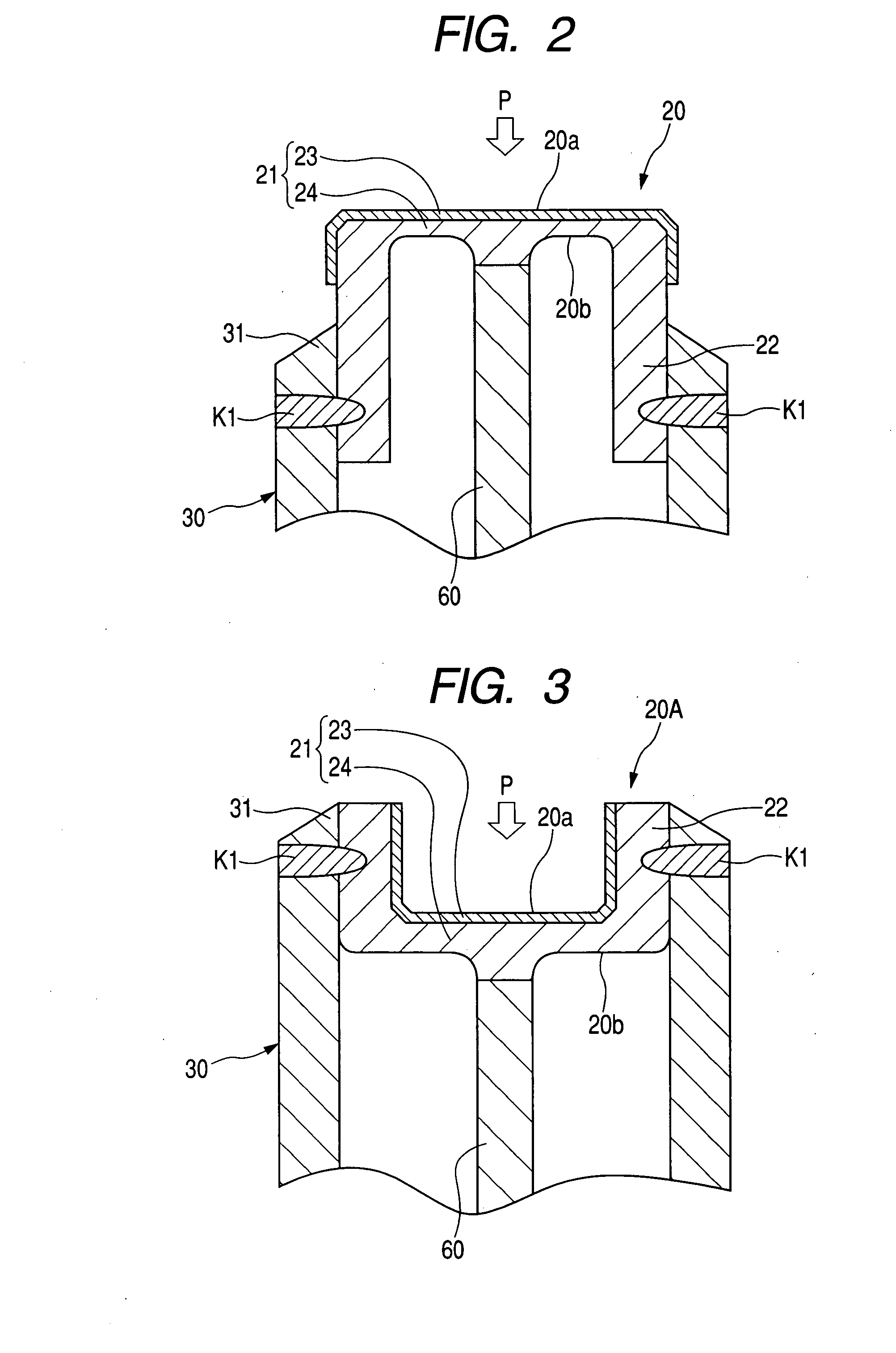
[0046]FIG. 3 is an enlarged view of a diaphragm attached to the stem 30 according to a second embodiment.
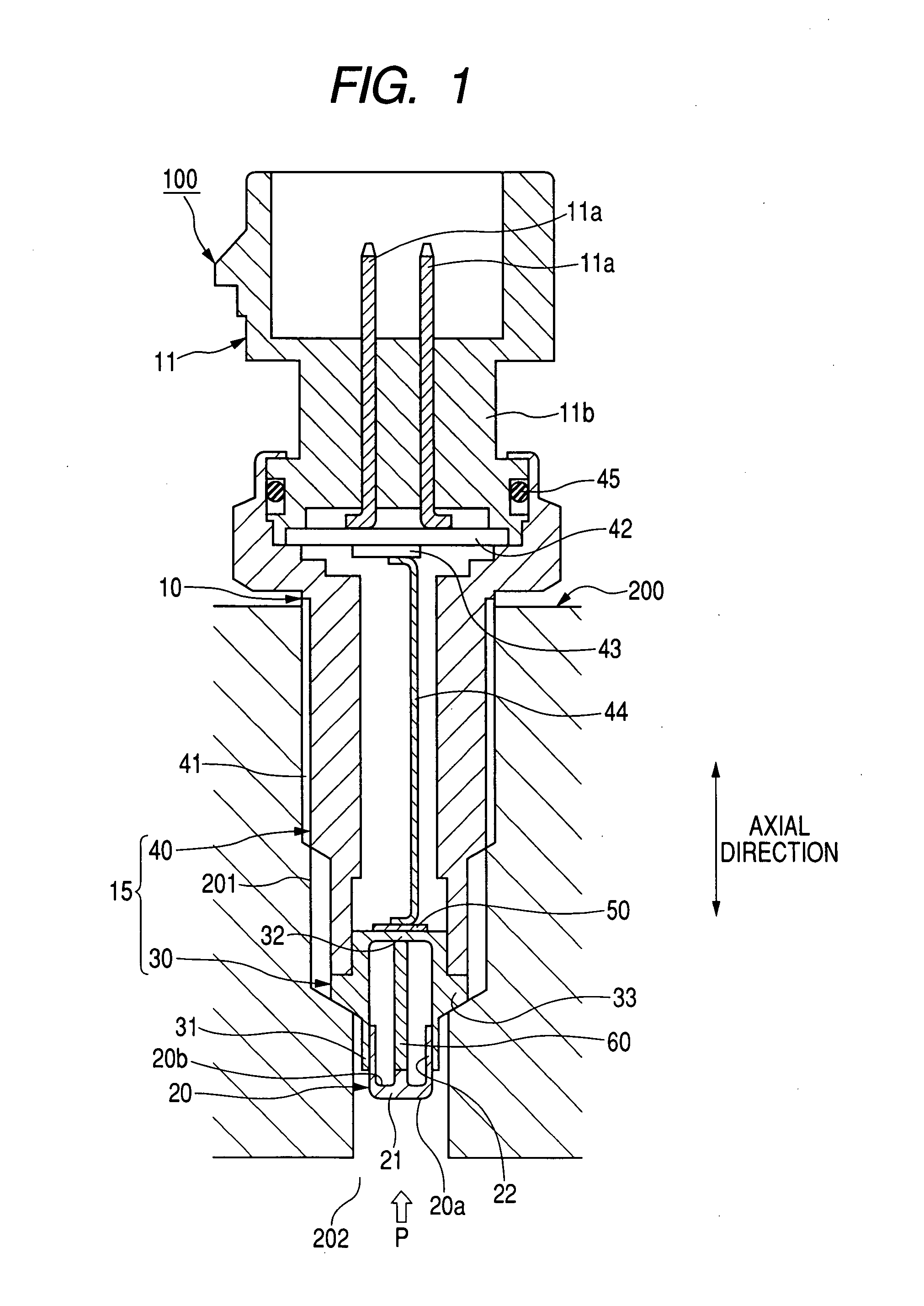
[0047]A diaphragm 20A shown in FIG. 3 is attached to the stem 30 of the pressure sensor 100 in the same manner as in the first embodiment. As shown in FIG. 3, the diaphragm 20A is formed in a cup shape opened toward the chamber 202 and has a bottom portion 21 with a flat front surface 20a exposed to the combustion gas. An end portion 22 of the diaphragm 20A is attached to the stem 30 by performing laser welding for the portion 22 and stem 30 along the circumferential direction. Therefore, the portion 22 and the stem 30 are fixed to each other in a fixing area K1.
[0048]The diaphragm 20A differs from the diaphragm 20 in that the diaphragm 20A is shaped so as to protrude the bottom portion 21 from the fixing area K1 toward the member 60 (or lower direction in FIG. 3). Therefore, the first layer 23 becomes an inner layer of the diaphragm 20A, and the second layer 24 becomes an outer ...
embodiment 3
[0058]The layers 23 and 24 according to the first embodiment are attached to each other as a lamination by rolling. However, the attachment between the layers 23 and 24 is not limited to the rolling process.
[0059]FIG. 4 is an enlarged view of a diaphragm attached to the stem 30 according to a third embodiment.
[0060]A diaphragm 20B shown in FIG. 4 is attached to the stem 30 of the pressure sensor 100 in the same manner as in the first embodiment. As shown in FIG. 4, in the same manner as in the first embodiment, the diaphragm 20B is formed in a cup shape and has the bottom portion 21 with the front surface 20a. The diaphragm 20C differs from the diaphragm 20 shown in FIG. 2 in that the layers 23 and 24 are attached to each other by an adhesive agent such as polyimide resin so as to face each other through an adhesive layer 25. The layers 23 and 24 are fixed to each other in a fixing area K2 by laser welding performed for the layers 23 and 24 along the circumferential direction of the...
PUM
 Abstract
Description
Claims
Application Information
 - R&D Engineer
- R&D Manager
- IP Professional
- Industry Leading Data Capabilities
- Powerful AI technology
- Patent DNA Extraction
Browse by: Latest US Patents, China's latest patents, Technical Efficacy Thesaurus, Application Domain, Technology Topic, Popular Technical Reports.
© 2024 PatSnap. All rights reserved.Legal|Privacy policy|Modern Slavery Act Transparency Statement|Sitemap|About US| Contact US: help@patsnap.com