Welding condition monitoring device

a condition monitoring and welding technology, applied in the direction of manufacturing tools, non-electric welding apparatus, television systems, etc., can solve the problems of insufficient image contrast, inability to present a complete image distinctly showing both the high luminance welding portion and the low luminance bead portion, and the object image taken by a single ccd camera does not allow the observer to grasp the welding

Inactive Publication Date: 2008-03-13
HONDA MOTOR CO LTD
View PDF7 Cites 90 Cited by
  • Summary
  • Abstract
  • Description
  • Claims
  • Application Information

AI Technical Summary

Benefits of technology

[0025] Another object of the present invention is to provide a welding condition monitoring device for observing a welding state of a welding work portion of an object being welded by a distant welding machine for welding the object with no contact therewith by a sequence of images taken therefrom by a CMOS type camera, wherein the CMOS type camera attached to the welding head is first adjusted to a specified angle at which the camera takes a bright spot (of laser beam) irradiating the welding portion of the object and then adjusts its level, i.e., the height level of the welding head with respect to the object by using a adjusting means in such a manner that the bright spot is always located at a specified position on the view seen by the CMOS type camera, thus maintaining the camera at a constant distance from the object being welded by the welding head.

Problems solved by technology

If an image sensor having a narrow dynamic range is applied for the above-described application, it cannot present a complete image distinctly showing both of a high luminance welding portion and a low luminance bead portion.
In case of monitoring a welding state of a welding work portion by an image taken therefrom by an image sensor using light sensor circuits each having a logarithmic output characteristic with a wide dynamic range, the image covering a wide range of luminosity from a very light portion to a dark portion may be observed but may suffer insufficient contrast of the image because of logarithmic compression of the luminance.
Accordingly, an object image taken by a single CCD camera does not allow the observer to grasp the welding states of the molten pool BA and the bead portion BB.
When a CCD camera is used for taking an image of the same object by alternately changing over the aperture size (or filter) from one suitable for taking an image of the light molten pool BA to another suitable for taking an image of the dark bead portion BB and reverse, it cannot achieve real-time monitoring of the states of the molten pool BA and the bead portion BB.
The above adjustment may result in appearing on the image a darkened invisible portion corresponding to a portion irradiated by a weakened laser beam in the teaching stage for positioning a laser beam thereon before the welding operation or may result in halation of the highlight portion on the image.
This requires the monitoring system to perform complicated operations.

Method used


Image

  • Welding condition monitoring device
  • Welding condition monitoring device
  • Welding condition monitoring device

Examples


Embodiment Construction

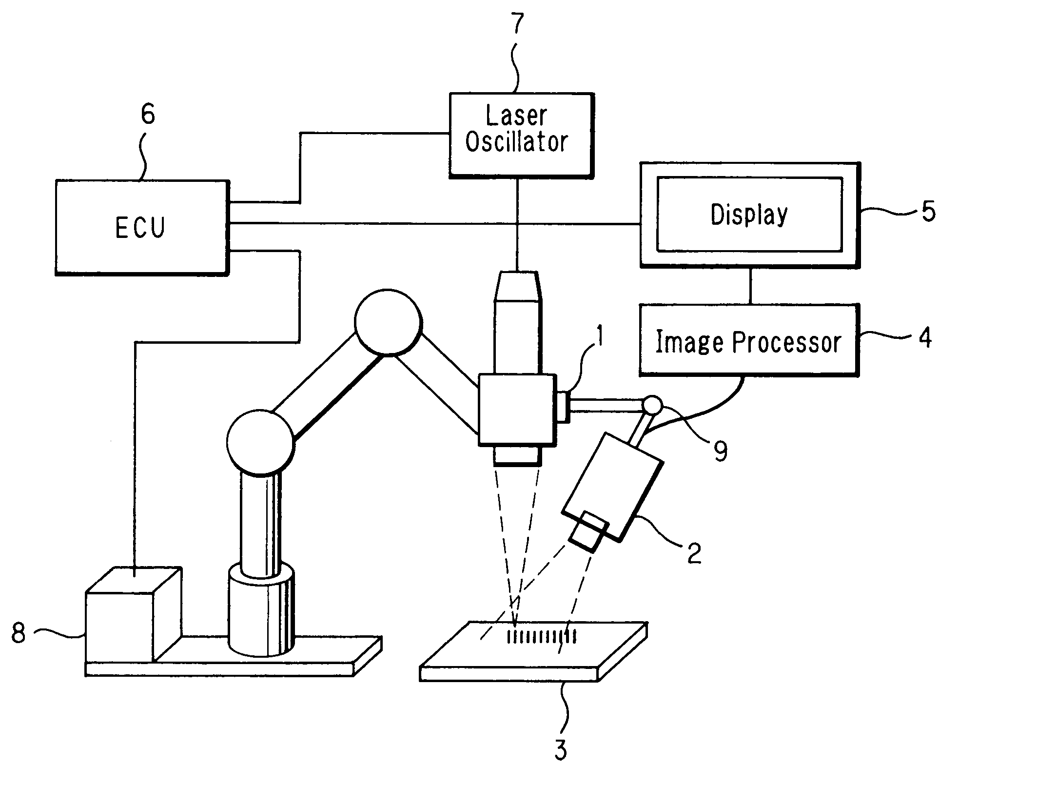
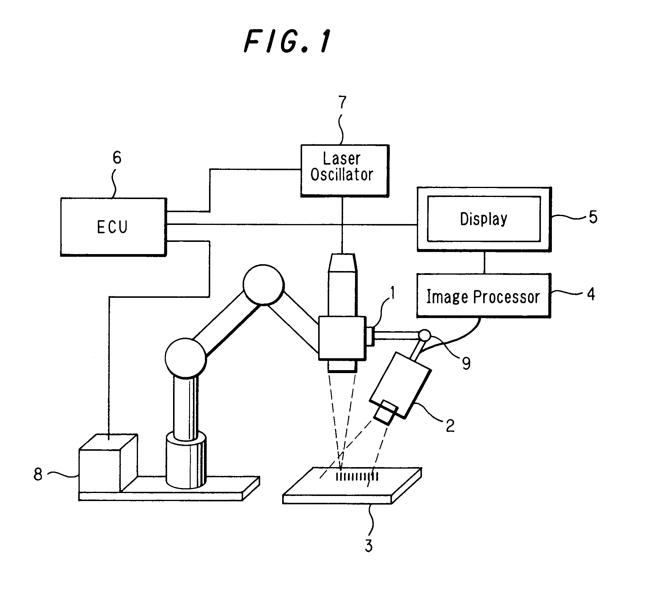
[0065]FIG. 1 illustrates an exemplary construction of a welding condition monitoring system in which a CMOS type camera 2 comprising an image sensor is attached to a portion of a welding head 1 of a laser beam welding robot for taking an image of a welding work portion of members 3 to be joined together. The image taken by the camera is transferred to an image processing unit 4 whereby it is processed and then displayed on a screen of a display unit 5. At the same time, the image processing unit 4 examines the welding condition based on data from the image taken by the CMOS camera and transfers the resultant data to an electronic control unit (ECU) 6 which in turn changeably controls parameters of welding conditions such as a welding position and laser beam intensity in accordance with the observed welding state. In FIG. 1, numerals 7 and 8 designate a laser oscillator and a robot driver respectively. All components are operated under the control from the ECU 6.

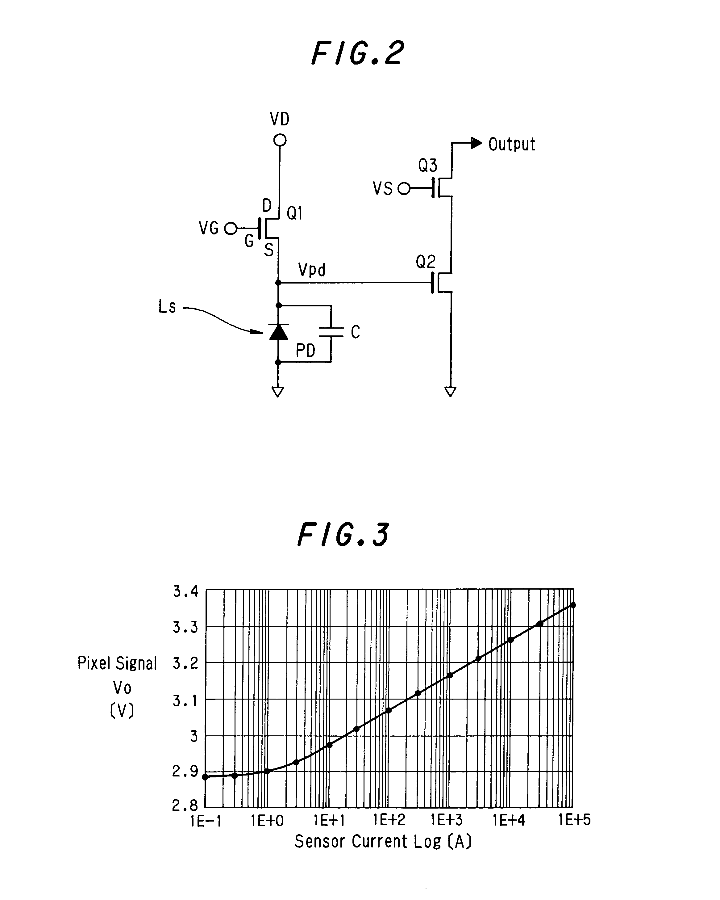
[0066] The CMOS type...


PUM

PropertyMeasurementUnit
currentaaaaaaaaaa
currentaaaaaaaaaa
luminanceaaaaaaaaaa

Abstract

A welding condition monitoring device for monitoring the welding state of a welding work portion by taking an image thereof by an image sensor having a wide dynamic range and capable of taking an image covering a very bright welding portion and relatively dark portion. The monitoring device selectively emphasizes the outputs of the image sensor for any of luminance areas of the image taken by the image sensor using a sensor output characteristic table and can provide an image clearly showing both the very bright welding portion and the dark bead portion with a sufficient contrast allowing an observer to reliably recognize the objects in the image.

Description

BACKGROUND OF THE INVENTION [0001] The present invention relates to a welding condition monitoring device capable of visually monitoring a welding state of a welding work portion of an object being weld by a welding machine by an image taken therefrom by an image sensor. [0002] Generally, the welding operation of a modern laser welding machine is monitored by an image taken from a currently welding position by an image sensor, which image is used for inspecting the welding conditions. [0003]FIG. 29 shows an image of a surface of members being joined together by the heat of a laser beam of a laser welder. The image is comprised of a welding portion of metal melted at high temperature by the heat of a laser beam, a molten pool and a bead formed by solidification of weld metal behind the molten pool. To estimate the quality of a weld joint to be formed, it is necessary to monitor a high luminance welding portion and a low luminance bead portion on the same image. For this purpose, it i...

Claims


Application Information

Patent Timeline
Patent Type & Authority Applications(United States)
IPC IPC(8): B23K31/12B23K26/00B23K9/095B23K26/03B23K26/20
CPCB23K9/0953B23K9/0956H04N5/35518B23K26/20B23K31/125B23K26/032B23K26/242H04N25/573
Inventor SEKI, HIDEOSHINOTSUKA, SUKEYUKIFURUKAWA, MAKOTOODA, KOJIOTSUKA, KEIJIKIRITA, JIROFUEKI, NOBUHIROWATANABE, HIRONORI
Owner HONDA MOTOR CO LTD
Why Eureka
Try Eureka