Lift detection adapted for navigation on a transparent structure

a technology of transparent structure and navigation, applied in the direction of counting objects on conveyors, instruments, geological measurements, etc., can solve the problem that the focusing optics are unable to be absorbed and the conventional lift detection techniques are ineffective over the distances required for practical lift detection

Inactive Publication Date: 2008-03-13
PIXART IMAGING INC
View PDF7 Cites 34 Cited by
  • Summary
  • Abstract
  • Description
  • Claims
  • Application Information

AI Technical Summary

Benefits of technology

[0006]In an embodiment, the pointing device is equipped with both a top surface lift detection system and an navigation sensor lift detection system. The navigation sensor lift detection system generates a lift status signal in response to image information from a navigation sensor array and the top surface lift detection system generates a lift status signal in response to detection of a beam that reflects off the surface upon which the pointing device sits wh...

Problems solved by technology

While an optical navigation device can be configured to support navigation tracking on both transparent and opaque structures without focusing optics, elimination...

Method used


Image

  • Lift detection adapted for navigation on a transparent structure
  • Lift detection adapted for navigation on a transparent structure
  • Lift detection adapted for navigation on a transparent structure

Examples


Embodiment Construction

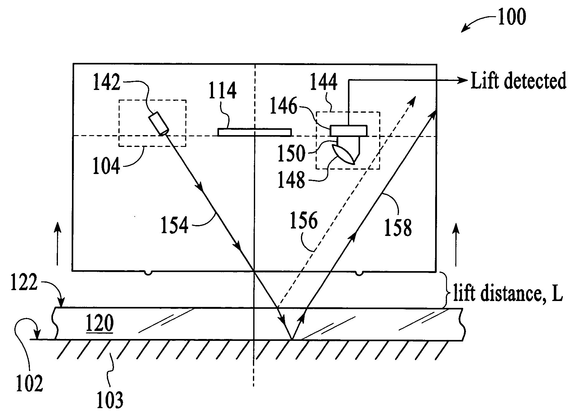
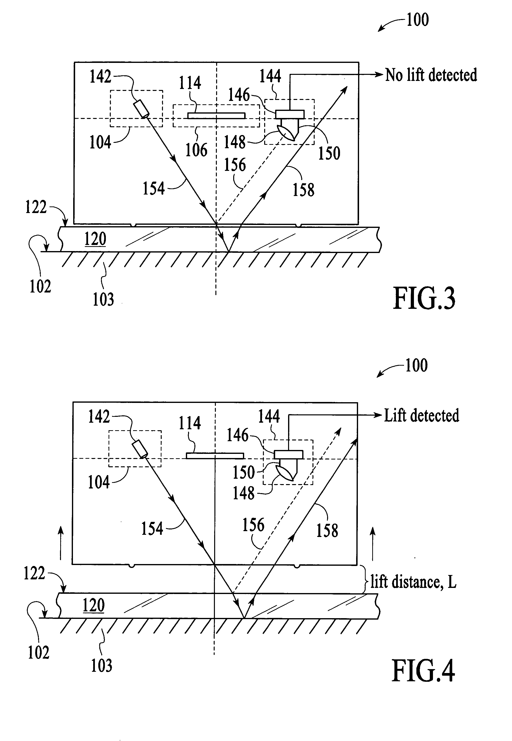
[0015]A pointing device such as an optical mouse is equipped with a top surface lift detection system that is able to provide lift detection whether the pointing device sits on a transparent structure or on an opaque structure. The top surface lift detection system relies on the separate detection of a beam that reflects off the surface upon which the pointing device sits to detect lift whether the pointing device sits on an opaque structure or a transparent structure.

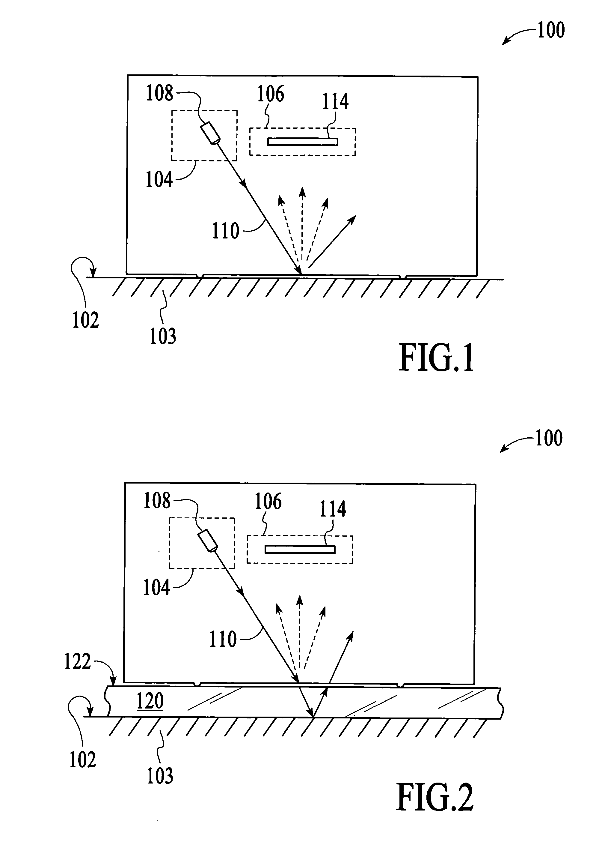
[0016]FIG. 1 is a cross-sectional view of an optical navigation device 100, referred to generally herein as a “pointing device,” which sits on and moves over the surface 102 of an opaque structure 103 such as a desktop. For purposes of this description, the pointing device may be viewed as having two principal components, an illumination system 104 and a navigation sensor system 106. The illumination system typically includes a light source 108 such as a light emitting diode (LED) and some optics (not shown), which tog...


PUM


Abstract

A pointing device such as an optical mouse is equipped with a top surface lift detection system that is able to provide lift detection whether the pointing device sits on a transparent structure or on an opaque structure. The top surface lift detection system relies on the separate detection of a light beam that reflects off the surface upon which the pointing device sits to detect lift whether the pointing devices sits on an opaque surface or a transparent surface.

Description

BACKGROUND OF THE INVENTION[0001]An optical navigation device, such as an optical mouse, typically includes an optical navigation sensor integrated circuit (IC) that functions as a miniature digital camera to continually collect images of a surface that the device is sitting on and to determine the speed and direction that the device is being moved across the surface by comparing sequentially recorded frames of image information. Image frames are collected at a very high rate, such as 1,500 image frames per second, and the resolution of the optical navigation sensor IC is high enough to detect very small movements of the device relative to the navigation surface.[0002]With an optical navigation device such as an optical mouse, there is a need to recognize when the device has been lifted off the navigation surface. This is important because the act of lifting the device off the navigation surface indicates that the user wants navigation tracking to be temporarily suspended. Detecting...

Claims


Application Information

Patent Timeline
IPC IPC(8): H01J40/14G06F3/038
CPCG06F3/0383G06F3/0317
Inventor LEE, WUI PINLEE, SAL MUN
Owner PIXART IMAGING INC
Why Eureka
Try Eureka