Method and device for the production of blown tubular film

a tubular film and production method technology, applied in the direction of auxillary shaping apparatus, ceramic shaping apparatus, applications, etc., can solve the problems of insufficient cooling at high output rate, short axial cooling range, and insufficient double cooling rings, etc., to facilitate production star

Inactive Publication Date: 2008-03-13
K DESIGN CO LTD
View PDF10 Cites 23 Cited by
  • Summary
  • Abstract
  • Description
  • Claims
  • Application Information

AI Technical Summary

Benefits of technology

[0008]It is an object of the present invention to provide a process and device for the production of blown tubular film to provide improved results regarding the distribution of the circumferential thickness variation of the tubular film. One objective is achieved by providing a process and device for of controlling the thickness profile of a blown tubular film.SUMMARY OF THE INVENTION
[0011]A process and device according to the invention provides that cooling gas flows are controllable in sectors in a circumferentially and variable manner. The cooling gas flows can be supplied along a considerable length of the production process from the exit of the tubular film from the nozzle extrusion die as far as close to the entry of the tubular film into a calibration basket without the effect of the cooling gas flows being lost through mixing or heating after a short distance in the direction of production. The ejection speed of the tubular film can be considerably increased due to the fact that the operating range of the circumferentially variably controllable cooling gas supply is been greatly extended. Thus, while quality is maintained, an increase in the production rate is been achieved.
[0018]By being able to control the axial distance between the cooling gas flows and cooling rings respectively, it is possible to ensure adaptation to different production speeds. This also facilitates the production start in that it becomes possible to provide access to the film nozzle of the extrusion die.

Problems solved by technology

This is also the case with a simple cooling ring with a supplementary cooling ring, however the effective axial cooling range is short such that cooling can be insufficient at high output rates.
On the other hand, a double cooling ring may not be sufficient since, before the substantial increase in the cross-section of the film tube at the second cooling ring occurs, substantial uniform cooling around the circumference may occur whereby any existing errors in the thickness profile are formed and remain.

Method used


Image

  • Method and device for the production of blown tubular film
  • Method and device for the production of blown tubular film
  • Method and device for the production of blown tubular film

Examples


Embodiment Construction

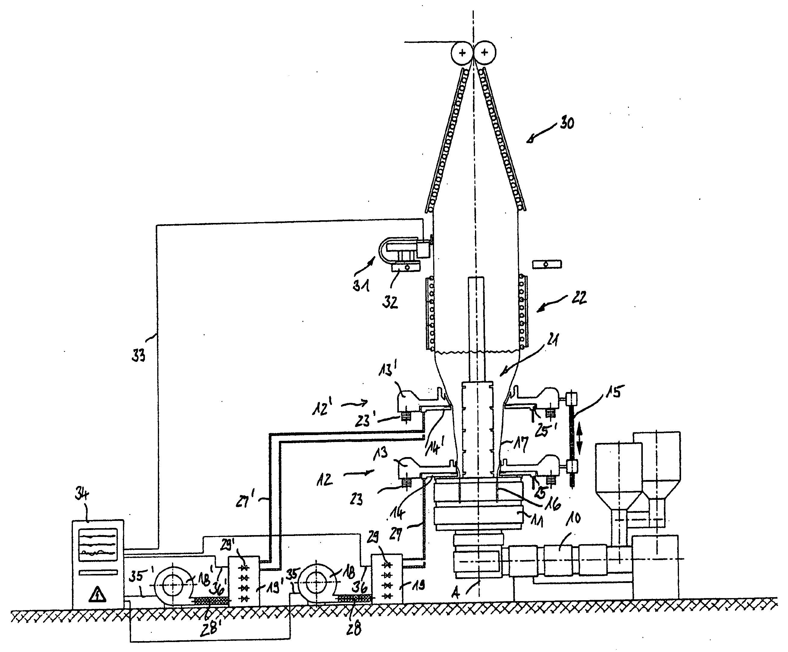
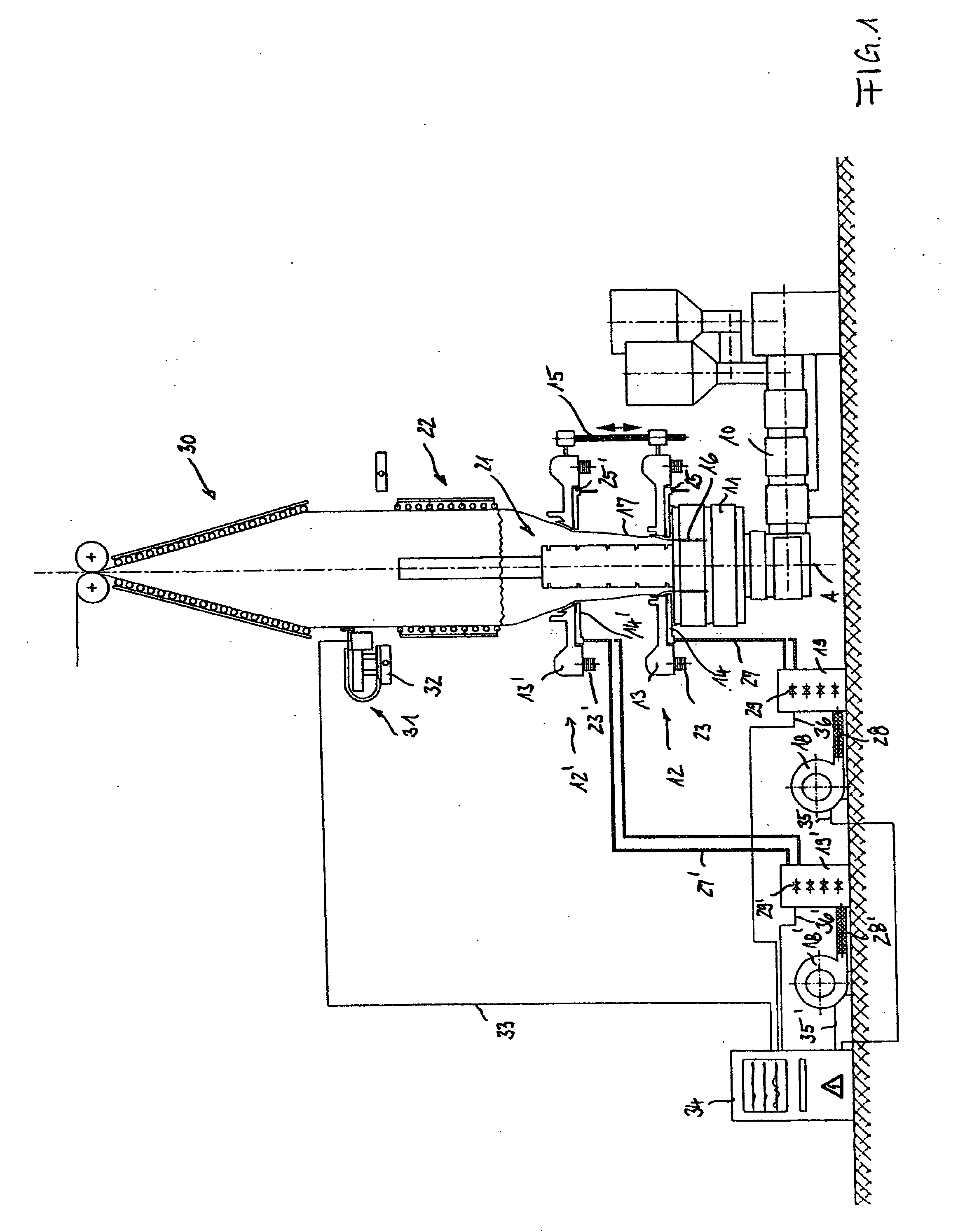
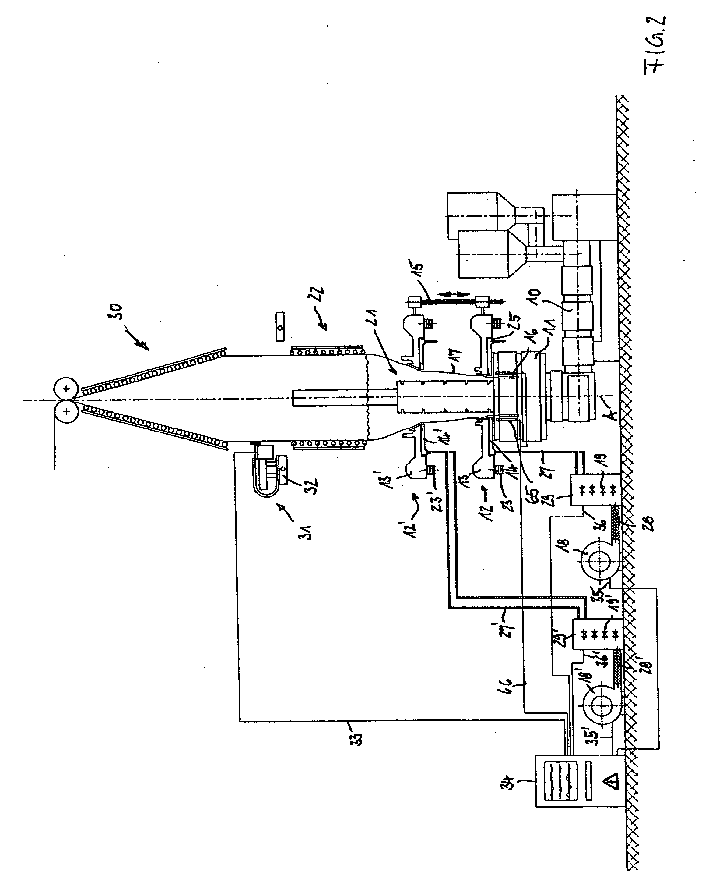
[0034]A device according to the invention shown in FIG. 1 comprises a film blowing extruder 10 with an extrusion die 11, a first cooling ring 12 with an annular channel 13 for a constantly uniformly emerging partial cooling gas flow and a segment disc 14 arranged underneath the latter, for a partial cooling gas flow controllable in sectors, as well as a second cooling ring 12′ arranged thereabove. A annular channel 13′ is provided for a constantly uniformly emerging partial cooling gas flow and a segment disc 14′ arranged underneath the latter, for a partial cooling gas flow controllable in sectors. Both cooling rings 12, 12′ serve to cool a film tube 17 emerging from an annular nozzle 16 at the extrusion die 11.

[0035]A circumferentially arranged measuring device 31 is provided for controlling the thickness profile of the film tube 17, which measuring device 31 scans the film thickness at the film tube 17 above a freezing limit. A control device 34 is provided which varies in sector...


PUM

PropertyMeasurementUnit
thicknessaaaaaaaaaa
volume flowaaaaaaaaaa
temperatureaaaaaaaaaa

Abstract

A process of controlling the thickness profile of a blown tubular film, consisting of thermoplastic plastics, around the circumference of same when producing blown film by means of blown film extruders, having a film extrusion die, wherein a measuring device measures the film thickness of the tubular film around the circumference and wherein a control device variably controls the cooling gas flow as a function of the measured film thicknesses around the circumference in sectors, wherein cooling gas flows are supplied from the outside in the direction of production in two separate planes, and wherein the cooling gas flows are controlled variably and in circumferential sectors around the circumference in the two planes in respect of their physical parameters.

Description

FIELD OF THE INVENTION[0001]The invention relates to a process of controlling the thickness profile during the production of blown tubular film, and devices for carrying out such a process. Tubular film leaving the annular nozzle of a blown film extruder has a thickness profile around the circumference of the tubular film. The thickness profile may comprise circumferentially distributed, thicker and thinner regions which are largely fixed in position. Such an uneven distribution of thickness around the circumference can have an adverse effect during the coiling and further processing of the tubular film.[0002]It is advantageous to reduce the deviations of the circumferential thickness profile at the early stage of producing the tubular film. When the tubular film is blown, i.e. when expanding the tube diameter, hotter regions are expanded to a greater extent and cooler regions to a lesser extent. Generally, the differences in the thickness of the tubular film around the circumferenc...

Claims


Application Information

Patent Timeline
Patent Type & Authority Applications(United States)
IPC IPC(8): B29C47/92B29C55/28B29C48/92
CPCB29C47/0026B29C47/883B29C47/8835B29C47/92B29C55/28B29C2947/92923B29C2947/92428B29C2947/926B29C2947/92647B29C2947/92704B29C2947/92904B29C2947/92152B29C48/92B29C2948/92704B29C48/10B29C48/9125B29C48/913B29C2948/92152B29C2948/92428B29C2948/926B29C2948/92647B29C2948/92904B29C2948/92923
Inventor ZIMMERMANN, RICHARDFAHLING, GERD
Owner K DESIGN CO LTD
Why Eureka
Try Eureka