Vending machine lock system

Inactive Publication Date: 2008-03-13
ILLINOIS TOOL WORKS INC
View PDF10 Cites 4 Cited by
  • Summary
  • Abstract
  • Description
  • Claims
  • Application Information

AI Technical Summary

Benefits of technology

[0006]The present invention provides a multi-point lock providing the increased security of two separate latch points, and a more uniform compression of the door gasket using a simple lever mechanism. The lever mechanism produces a hooking and pulling action that provides a large latch-throw suitable for gasketed doors, and provides high, end-stroke compression of the gasket to seal the gasket and resist unauthorized opening of the door.

Problems solved by technology

The time required to compress the gasket using a T-handle system (and conversely, to release the door by uncompressing the gasket) increases the time and cost of routine service of the vending machine, for example, to replenish stock and collect money.
A single radio signal could coordinate these multiple locks, however, current motorized designs are prohibitively expensive.

Method used


Image

  • Vending machine lock system
  • Vending machine lock system
  • Vending machine lock system

Examples


Embodiment Construction

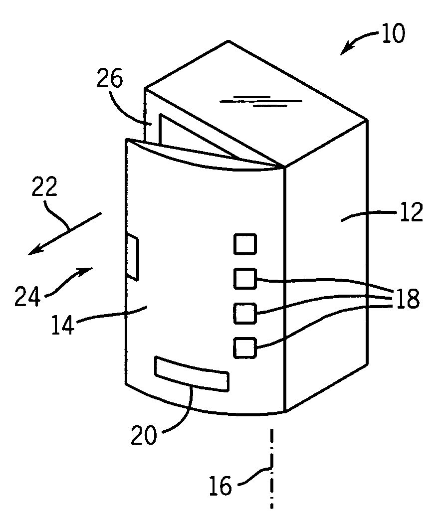
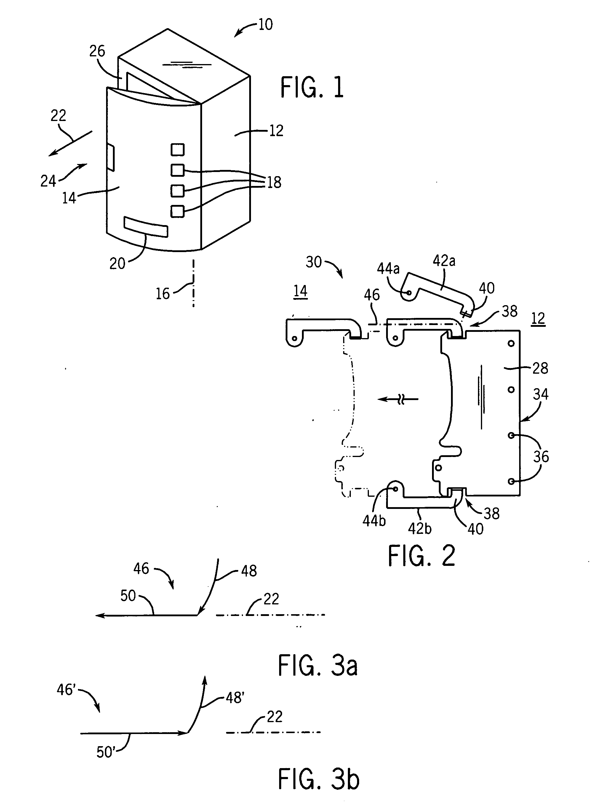
[0041]Referring now to FIG. 1, a vending machine 10 suitable for use with the present invention may include a cabinet 12, being generally a metal box sized to hold a vending apparatus (not shown), and having an open front that may be covered by a door 14. The door 14 may display on its front surface vending controls 18, including product selection buttons and money handling apparatus, and may include a dispensing slot 20.

[0042]The door 14 may hinge about an axis 16, being in this example, a vertical axis aligned with a right side of the open face of the cabinet 12, to move between a closed position covering the opening of the cabinet 12, and an open position providing access to the interior of the cabinet 12. A compressible gasket 26 may be attached to the periphery of the open face of the cabinet 12 or the corresponding surface of the door 14 to seal the door 14 against the cabinet 12 when the door 14 is closed.

[0043]During the initial stages of opening the door 17 and the latter s...


PUM


Abstract

A motorized lock for a vending machine provides a simple lever mechanism that provides two separate points of engagement between the door and the machine to resist tampering and provide for more even pull in of a gasketed door.

Description

CROSS-REFERENCE TO RELATED APPLICATIONSSTATEMENT REGARDING FEDERALLY SPONSORED RESEARCH OR DEVELOPMENTBACKGROUND OF THE INVENTION[0001]The present invention relates to vending machines and in particular to a motorized lock assembly for such vending machines.[0002]Vending machines, such as may automatically dispense products to consumers, may provide a cabinet for holding the products to be dispensed and money handling machinery. The cabinet is normally covered by a lockable door that may, for example, extend over the entire front face of the vending machine, and which may seal the interior of the cabinet from the environment, often by means of a large flexible gasket extending around the perimeter of the door.[0003]The lock of the vending machine door must both hold the door securely and provide for compression of the gasket to fully close the door. A common lock suitable for this purpose provides a pop-out T-handle that may be rotated to compress the gasket by drawing the handle in...

Claims


Application Information

Patent Timeline
IPC IPC(8): E05C3/06
CPCE05B47/0002E05B47/0012E05B47/023E05B63/127G07F9/10E05B2047/0068E05C9/043E05C9/1883E05B2047/0024Y10S292/11Y10S292/68Y10T70/5761Y10T70/7062Y10T292/081Y10T292/0848Y10T292/086Y10T292/0951Y10T292/0959Y10T292/1082Y10T292/444
Inventor HAPKE, KENYON A.
Owner ILLINOIS TOOL WORKS INC
Why Eureka
Try Eureka