Vehicle low cost braking aerostabilizer

a technology of aerostabilizer and vehicle, which is applied in the field of aerostabilizers, can solve the problems of out of the reach cost wise of most potential users, too expensive for the average user, and achieve the effect of low cos

Inactive Publication Date: 2008-03-13
BROWN ALLAN L +1
View PDF19 Cites 23 Cited by
  • Summary
  • Abstract
  • Description
  • Claims
  • Application Information

AI Technical Summary

Benefits of technology

[0004]A principal object of the invention is to prov

Problems solved by technology

They are too expensive for the average user.
This makes such brakin

Method used


Image

  • Vehicle low cost braking aerostabilizer
  • Vehicle low cost braking aerostabilizer
  • Vehicle low cost braking aerostabilizer

Examples


Embodiment Construction

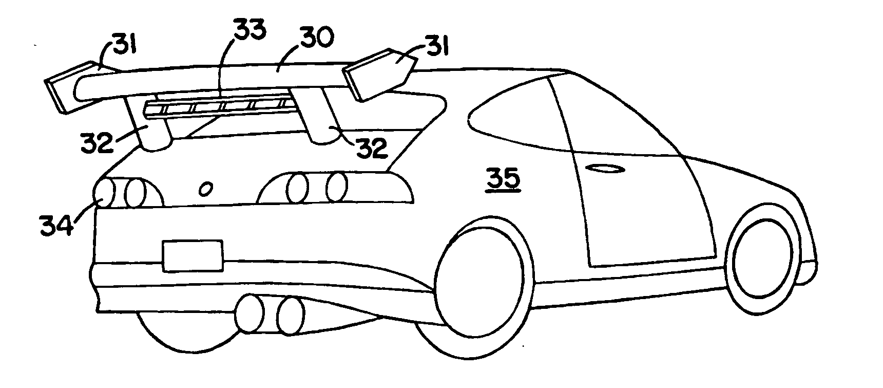
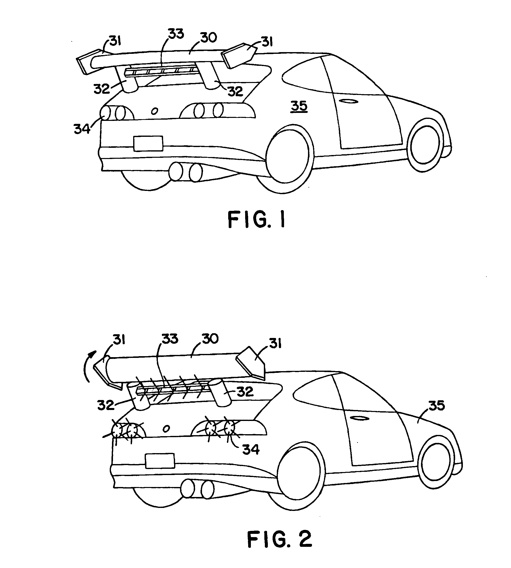
[0039]FIG. 1 presents a typical vehicle 35 with the instant invention low cost braking aerostabilizer 30 installed. In this example the aerostabilizer 30 is in its more horizontal non-braking position. Items shown in this preferred embodiment of the invention include: vehicle brake lights 34, aerostabilizer support stanchions 32, aerostabilizer end caps 31, and aerostabilizer brake lights 33. Note that more current cosmetic design thinking is to avoid the stanchions 32 and have the pneumatic cylinder internal to the aerostabilizer 30 itself or internal to a part of the vehicle 35 such as the vehicle's trunk.

[0040]FIG. 2 is an illustration showing the same vehicle 35 but with the braking aerostabilizer 30 in its more vertical braking orientation.

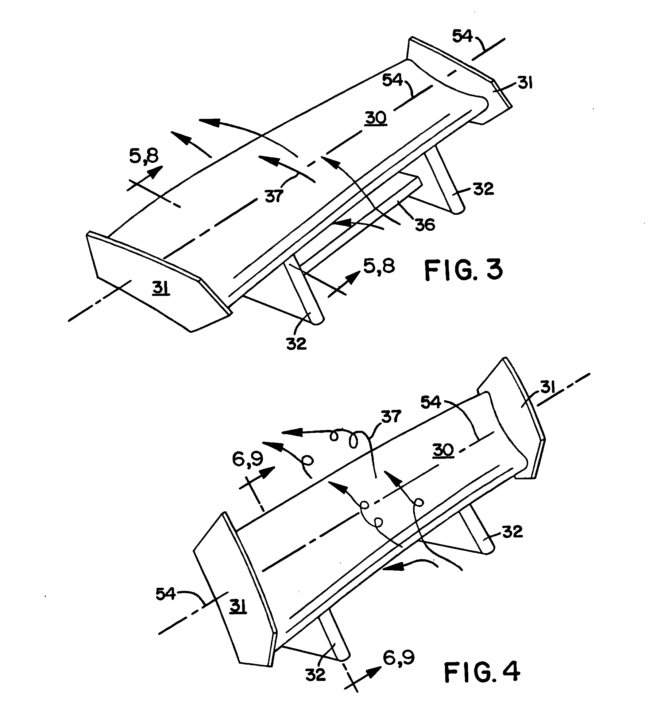
[0041]FIG. 3 shows the aerostabilizer 30 independent of a vehicle. It is in its more horizontal non-braking orientation here. The rotational axis 54 of the aerostabilizer 30, air flow arrows 37, and a brace 36 connecting the two support stanc...


PUM


Abstract

This invention defines a low cost easily installed aerostabilizer, more commonly called a wing or spoiler, for vehicles that rises from a more horizontal than vertical orientation that it maintains at constant or accelerating speeds to a more vertical than horizontal orientation during braking of the vehicle. Power for change to the more vertical orientation is provided from either vacuum or pressure applied to a pneumatic powering device. Low cost is maintained by use of vacuum from the vehicle's engine and/or from gas pressure from the vehicle's spare tire with other sources for either vacuum or gas pressure optional. Direction of pneumatic forces is made by braking valves that preferably derive their power from the vehicle's brake system.

Description

BACKGROUND OF THE INVENTION[0001]This invention relates to the field of aerostabilizers, more commonly called wings or spoilers, used on motor vehicles to enhance the vehicle's stability and, when reoriented to a more vertical orientation during braking by powered actuators, enhance the vehicle's stopping ability. When used for braking they are sometimes called braking wings or more correctly braking aerostabilizers. Braking aerostabilizers have been successfully employed on high speed race cars, expensive sport cars, and customized vehicles.[0002]The reason that such braking aerostabilizers have not seen widespread application is simple. They are too expensive for the average user. The aerostabilizers themselves are generally affordable; however, adding an electric actuator motor and its controls, hydraulic actuator system including a hydraulic pump and controls, or other prior art braking movement powering means can easily triple the cost. This makes such braking aerostabilizers o...

Claims


Application Information

Patent Timeline
IPC IPC(8): B62D35/00
CPCB62D35/007B60T1/16
Inventor BROWN, ALLAN L.BURG, DONALD E.
Owner BROWN ALLAN L
Why Eureka
Try Eureka