Power supply device

Inactive Publication Date: 2008-03-13
SANYO ELECTRIC CO LTD
View PDF2 Cites 8 Cited by
  • Summary
  • Abstract
  • Description
  • Claims
  • Application Information

AI Technical Summary

Benefits of technology

[0012]In the aforementioned power supply device detects the respective voltage values of the battery modules that compose the two battery blocks by means of the separate voltage management ICs but has a feature that solves factors that cause out of the balance of the remaining capacity amounts of the two battery blocks. The reason is that, in the aforementioned power supply device, the power lines of both the voltage management ICs are connected to the positive-side and negative-side output terminals of the battery equipment that includes the serially-connected positive-side and negative-side battery blocks so that electric power is equally supplied to each voltage management IC from all the battery modules.

Problems solved by technology

The reason is that there is unevenness in production processes and the like.
The reason is that the charging capacity is limited by the battery block with smaller remaining capacity, and the discharging capacity is limited by the battery block with larger remaining capacity.
To prevent this adverse effect, although it is conceivable that light emitting and receptiv

Method used


Image

  • Power supply device
  • Power supply device
  • Power supply device

Examples


Example

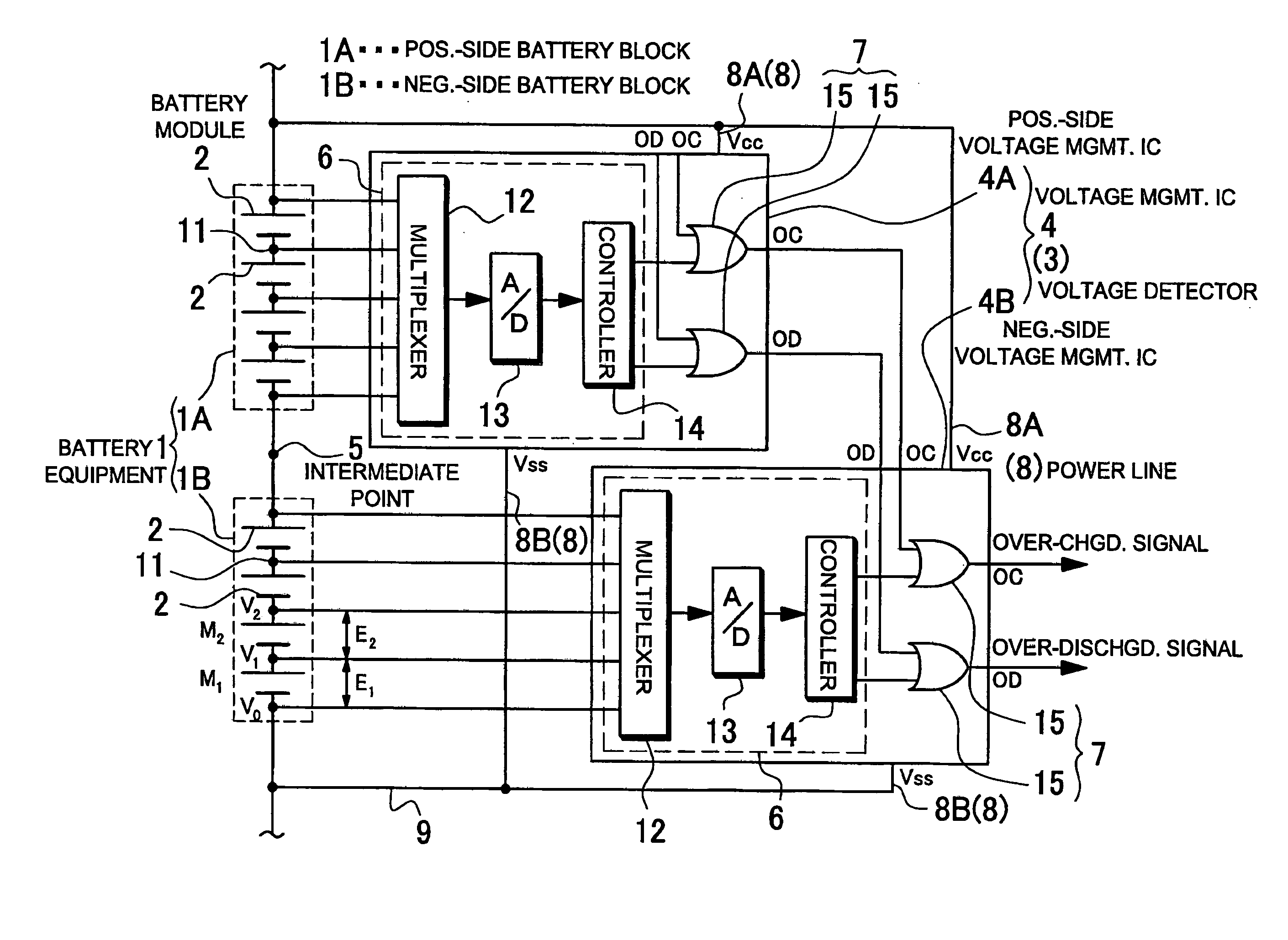
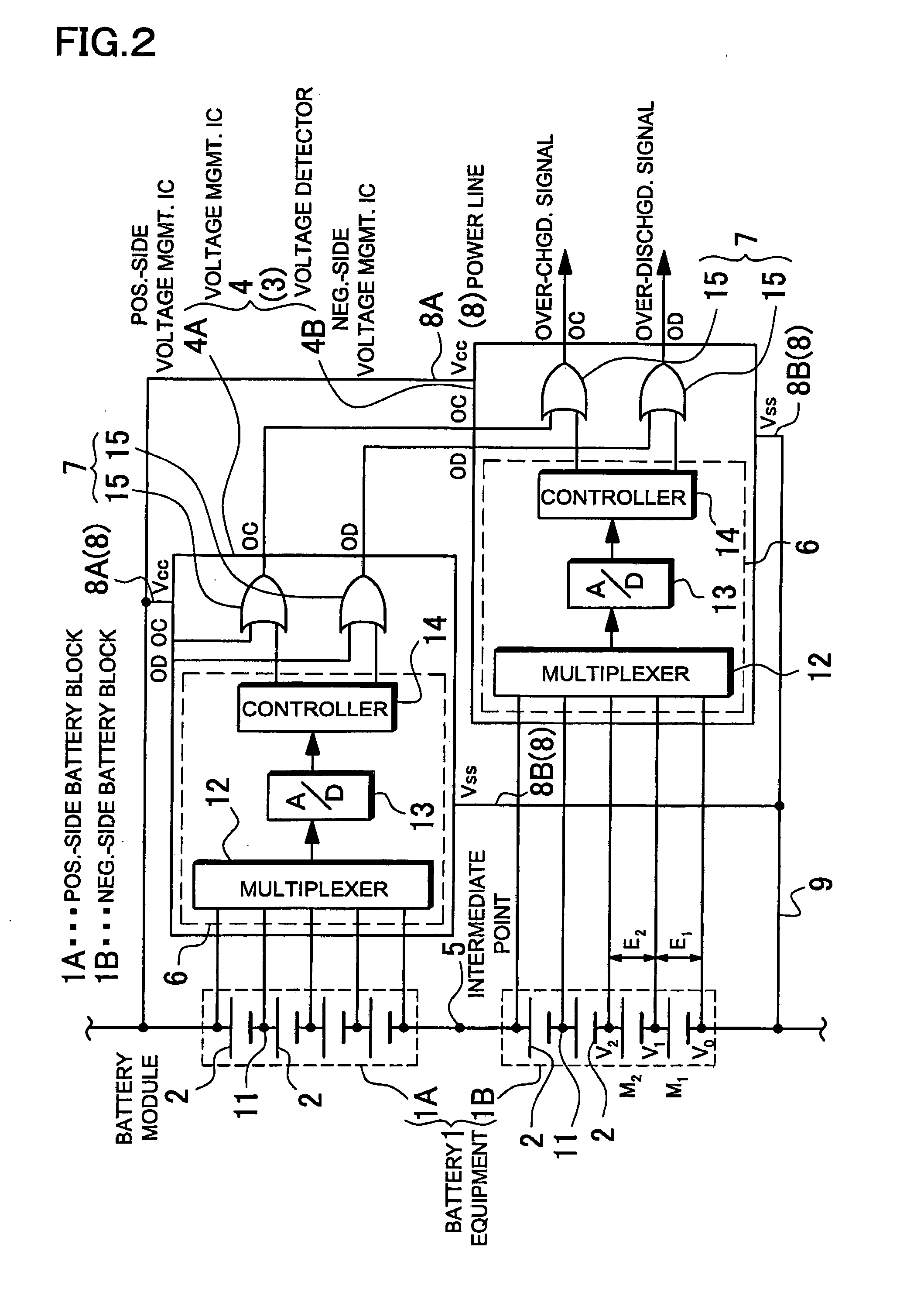
[0019]A power supply device shown in FIG. 2 includes battery equipment 1 and voltage detecting circuitry 3 that detects the respective voltage values of battery modules 2 that compose the battery equipment 1. In the battery equipment 1, two, positive-side and negative-side battery blocks 1A and 1B are serially connected to each other at an intermediate point 5.

[0020]The battery equipment 1 includes the positive-side and negative-side battery blocks 1A and 1B that are serially connected to each other. The positive-side battery block 1A is connected on the positive side with respect to the intermediate point 5. The negative-side battery block 1B is connected on the negative side with respect to the intermediate point 5.

[0021]In the power supply device shown in FIG. 2, the battery equipment 1 is divided into two blocks of the positive-side and negative-side battery blocks 1A and 1B. In order to separately detect the respective voltage values of the serially-connected battery modules 2,...


PUM


Abstract

A power supply device includes battery equipment and voltage detecting circuitry. The battery equipment includes positive-side and negative-side battery blocks that are connected to each other at a reference midpoint. The voltage detecting circuitry detects the respective voltage values of serially-connected battery modules of the battery equipment. The voltage detecting circuitry includes positive-side and negative side voltage management ICs with respect to the reference midpoint. The positive-side and negative side voltage management ICs manage the voltage conditions of the battery modules in the positive-side and negative-side battery blocks, respectively. Positive-side and negative-side voltage power lines of each of the positive-side and negative side voltage management ICs are connected to positive-side and negative-side output terminals of the battery equipment so that all the battery modules supply electric power to each of the voltage management ICs. The voltage management ICs have a common ground line.

Description

BACKGROUND OF THE INVENTION[0001]1. Field of the Invention[0002]The present invention relates to a power supply device such as a power supply for power tools and a backup power supply, and in particular to a power supply device that includes multiple battery modules that are serially connected to each other.[0003]2. Description of the Related Art[0004]Power supply devices such as a power supply for power tools and a backup power supply include multiple battery modules that are serially connected to each other in order to increase the output of the power supply devices. Thus, the power supply devices have high output. The reason is that the output of the power supply devices is proportional to the product of voltage and current of the battery modules. For example, in the case of a power tools that includes multiple battery modules that are serially connected to each other, the maximum output voltage is increased to 42 V, and in the case of a backup power supply that includes multiple...

Claims


Application Information

Patent Timeline
IPC IPC(8): H02J7/00H02J9/00G01R31/36H02J7/02
CPCH02J7/0021H02J7/00302H02J7/0014H02J7/00306H02J7/0049
Inventor YAMAMOTO, HIROYOSHI
Owner SANYO ELECTRIC CO LTD
Why Eureka
Try Eureka