
Low Supply Voltage, Large Output Swing, Source-Terminated Output Driver for High Speed AC-coupled Double-Termination Serial Links

a technology of ac-coupled double-termination serial link and output driver, which is applied in the direction of logic circuit, electrical apparatus, pulse technique, etc., can solve the problems of reducing the output impedance of the cml driver, reducing the operating speed of the circuit, and continually reducing the chip supply voltag

Inactive Publication Date: 2008-03-13
PARADE TECH
View PDF2 Cites 15 Cited by
  • Summary
  • Abstract
  • Description
  • Claims
  • Application Information

AI Technical Summary

Problems solved by technology

As data transfer requirements increase for both on-chip and inter-chip applications, transfer speed remains one of the most critical issues in modern integrated circuit design.
However, recent trends are to continually decrease chip supply voltages.
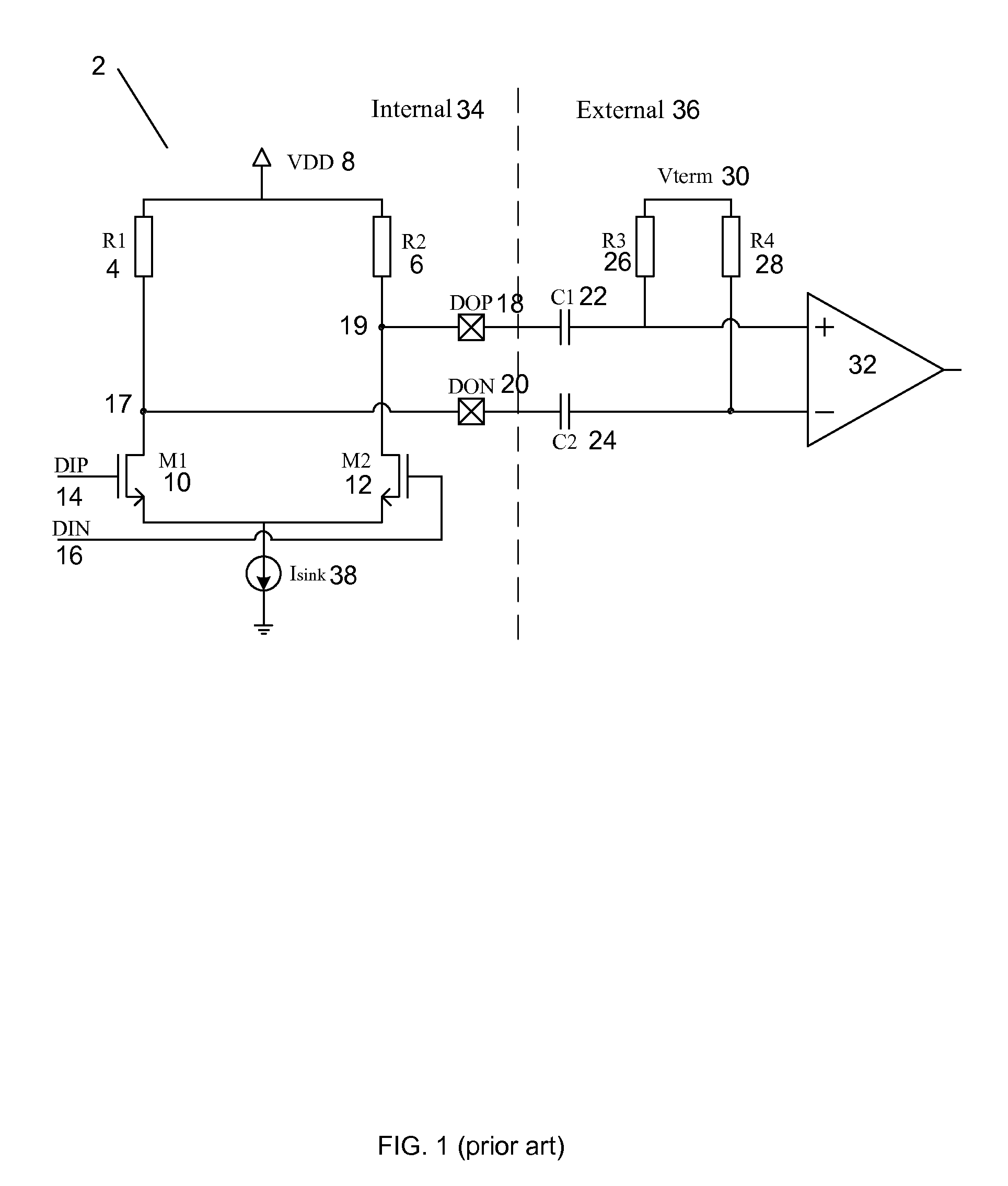
If transistors M110 and M212 are not operating in saturation range, a larger transistor is required to switch the large sink current, thereby decreasing operating speed of the circuit.
Furthermore, if transistors M110 and M212 are not operating in saturation range, the turn on resistance of the transistors decreases the CML driver output impedance, thereby decreasing performance of the CML driver.
However, raising the supply voltage increases the power consumption of the circuit.
A higher supply voltage also requires greater reliability of the semiconductor devices, resulting in greater engineering effort and higher costs.
Furthermore, for deep submicron semiconductor devices, a higher supply voltage may not always be feasible.

Method used


Image

  • Low Supply Voltage, Large Output Swing, Source-Terminated Output Driver for High Speed AC-coupled Double-Termination Serial Links
  • Low Supply Voltage, Large Output Swing, Source-Terminated Output Driver for High Speed AC-coupled Double-Termination Serial Links
  • Low Supply Voltage, Large Output Swing, Source-Terminated Output Driver for High Speed AC-coupled Double-Termination Serial Links

Examples


Embodiment Construction

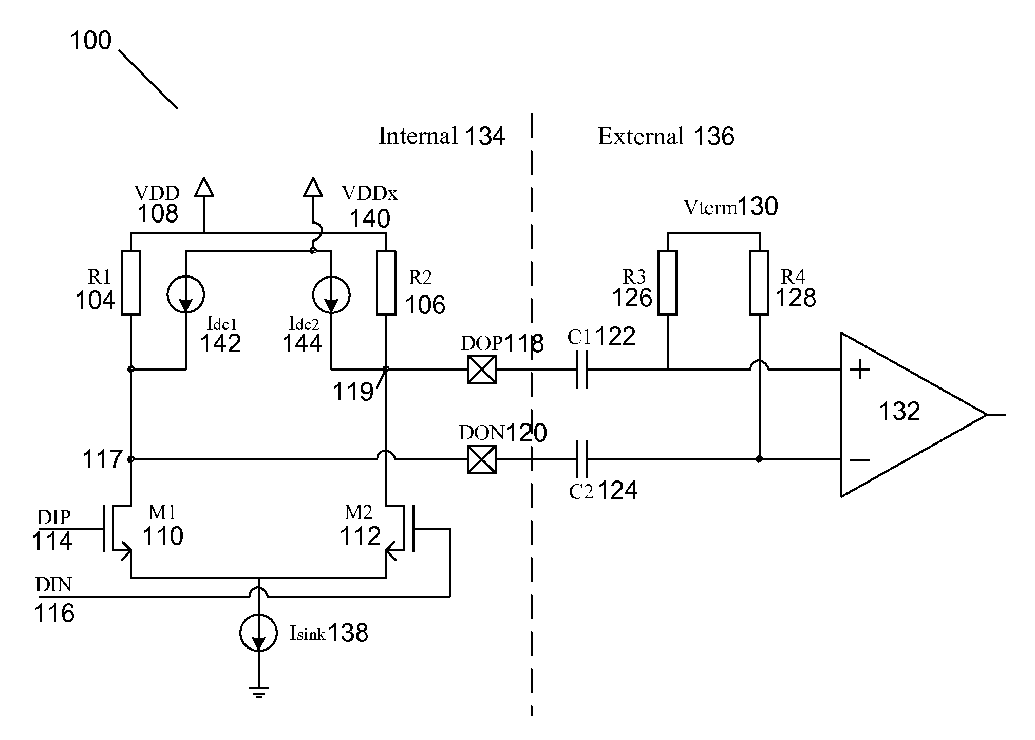
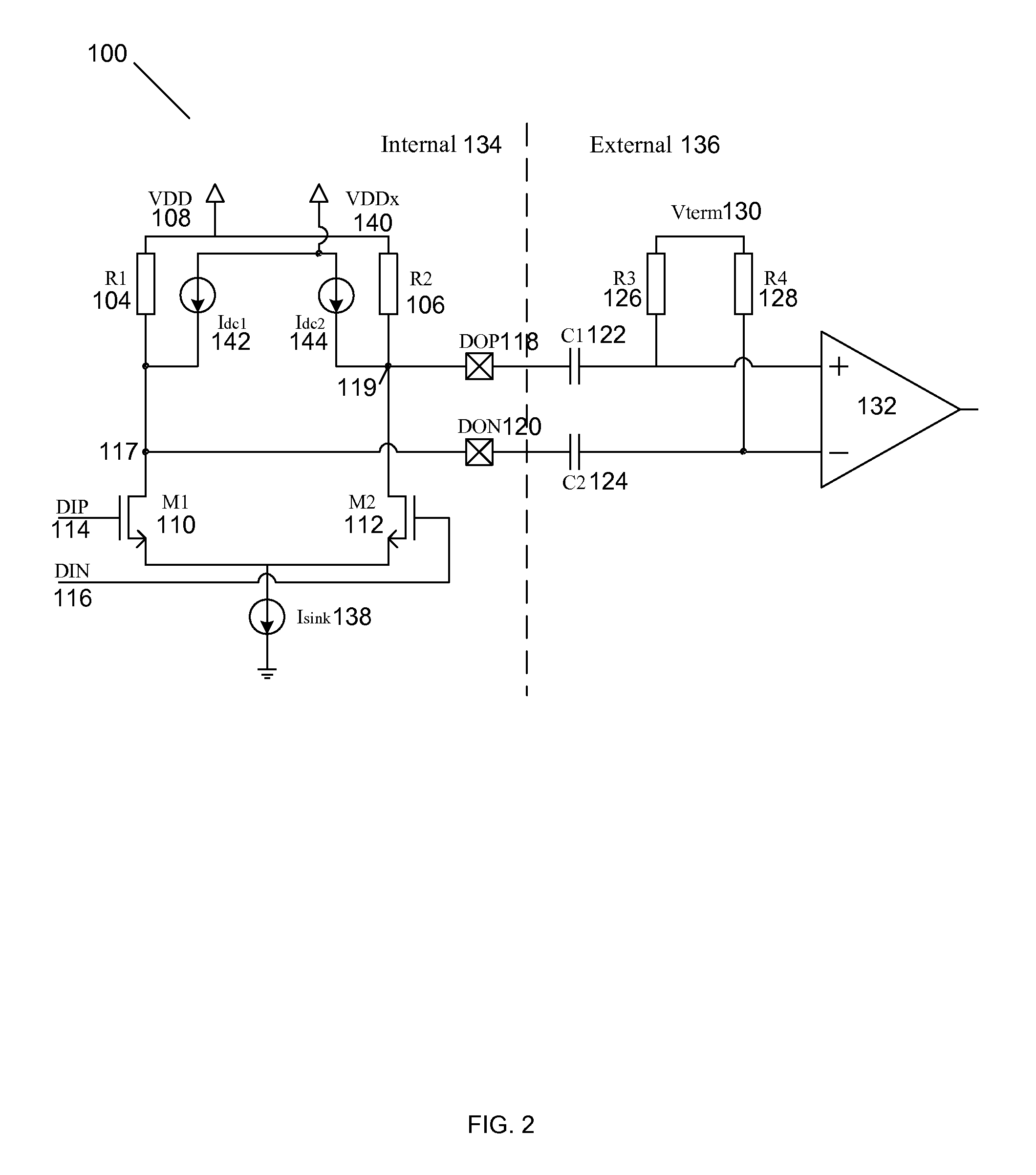
[0017]Systems and methods for low supply voltage, large output swing, source-terminated output driver for high speed ac-coupled double-termination serial links are disclosed. The following description is presented to enable any person skilled in the art to make and use the invention. Descriptions of specific embodiments and applications are provided only as examples and various modifications will be readily apparent to those skilled in the art. The general principles defined herein may be applied to other embodiments and applications without departing from the spirit and scope of the invention. Thus, the present invention is to be accorded the widest scope encompassing numerous alternatives, modifications and equivalents consistent with the principles and features disclosed herein. For purpose of clarity, details relating to technical material that is known in the technical fields related to the invention have not been described in detail so as not to unnecessarily obscure the prese...


PUM


Abstract

A current mode logic circuit includes a current mode logic driver circuit and a transistor biasing improvement circuit. The transistor biasing improvement circuit includes a first current source coupled to a first output node of the current mode logic driver circuit and a second current source coupled to a second output node of the current mode logic driver circuit. The first current source and the second current source raise a common mode voltage at the first output node and the second output node.

Description

BACKGROUND OF THE INVENTION[0001]As data transfer requirements increase for both on-chip and inter-chip applications, transfer speed remains one of the most critical issues in modern integrated circuit design. Current mode logic (CML) is widely used in modern high speed data path designs for its superior speed performance. Referring to FIG. 1, a conventional approach to implement an AC-coupled double termination data transmission link is illustrated. A CML driver circuit 2 located internal to an integrated circuit chip 34 consists of a differential pair of transistors NMOS transistor M110, NMOS transistor M212, source termination resistors R14, R26, and a current source Isink 38 that feeds the sources of the differential transistor pair. For any high speed data transmission over wireline, source termination resistors are used to reduce the reflections and thereby improve signal quality.[0002]The CML driver circuit 2 utilizes NMOS transistors M110 and M212 as a differential logic pai...

Claims


Application Information

Patent Timeline
Patent Type & Authority Applications(United States)
IPC IPC(8): H03K19/086
CPCH03K19/018528
Inventor XU, FENGYU, QUANQU, MING
Owner PARADE TECH
Learn More