Variable resonator, variable bandwidth filter, and electric circuit device

a variable bandwidth filter and resonator technology, applied in the direction of resonators, electrical equipment, waveguides, etc., can solve the problems of large device size, inability to operate devices at frequencies other than frequencies, and increase the scale, so as to reduce the influence of insertion loss, reduce the loss of the passband of the signal, and change the effect of bandwidth

Inactive Publication Date: 2008-03-13
NTT DOCOMO INC
View PDF8 Cites 8 Cited by
  • Summary
  • Abstract
  • Description
  • Claims
  • Application Information

AI Technical Summary

Benefits of technology

[0025]According to the present invention, a given circuit switch is selected from a plurality of circuit switches and is turned on (electrically connected) and thus it is possible to largely change a bandwidth while keeping a resonance frequency constant.
[0026]Further, in the variable resonator of the present invention, the loss of a signal at the resonance frequency is mainly controlled by a conductor line composing the variable resonator, thereby reducing the influence of an insertion loss caused by a circuit switch and so on. For this reason, even when a filter is configured using a circuit switch having a large loss for the variable resonator, it is possible to reduce the loss of the passband of a signal.
[0027]Further, in an electric circuit device of the present invention, by using the variable resonator of the present invention, it is possible to largely change a bandwidth around the resonance frequency and suppress an insertion loss caused by connecting the variable resonator.

Problems solved by technology

This method requires filters as many as required number of bandwidths and thus increases the scale of the circuit, resulting in a large device size.
Further, such devices cannot be operated at frequencies other than frequencies having the frequency characteristics of prepared filters.

Method used


Image

  • Variable resonator, variable bandwidth filter, and electric circuit device
  • Variable resonator, variable bandwidth filter, and electric circuit device
  • Variable resonator, variable bandwidth filter, and electric circuit device

Examples


Embodiment Construction

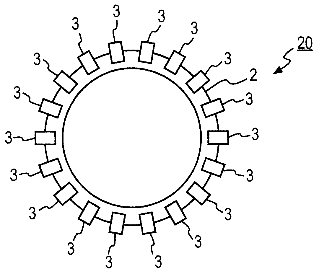
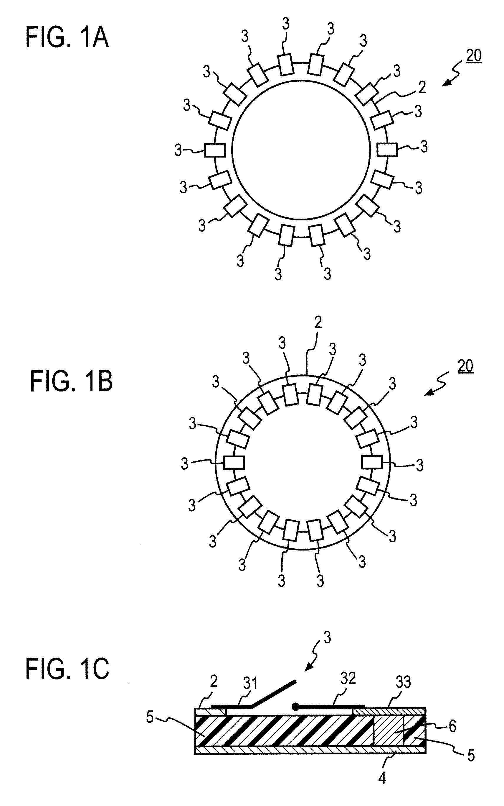
[0128]FIGS. 1A and 1B show variable resonators 20 of the present invention having ring-shaped microstrip line structures of two patterns. FIG. 1C is a cross-sectional example in which the ring of the variable resonator 20 of FIG. 1A or 1B is cut on the position of one switch 3. The variable resonators 20 of FIGS. 1A and 1B are each made up of a ring-shaped conductor line 2 (hereinafter, simply will be referred to as a ring-shaped line) and the switches 3 which are at least two circuit switches. “Ring-shaped” does not always have to be a circular shape, as will be described later, as long as the line forms a closed loop. As shown in the cross-sectional view of FIG. 1C, the ring-shaped line 2 is formed of a metal on one of the surfaces of a dielectric substrate 5. The dielectric substrate 5 has a ground conductor 4 formed of a metal on the opposite surface (will be referred to as the backside) from the surface having the ring-shaped line 2. The switch 3 has one end 31 electrically con...


PUM


Abstract

A variable resonator includes a ring-shaped conductor line (2) which is provided on a dielectric substrate (5) and has a circumferential length of a wavelength at a resonance frequency or an integral multiple of the wavelength, and at least two circuit switches (31, 32), wherein the circuit switches (31, 32) have one ends (31) electrically connected to the ring-shaped conductor line (2) and the other ends (32) electrically connected to a ground conductor (4) formed on the dielectric substrate (5), electrical connection/disconnection between the ground conductor (4) and ring-shaped conductor line (2) can be switched, and the one ends (31) of the circuit switches (31, 32) are connected to the ring-shaped conductor line (2) on different portions.

Description

TECHNICAL FIELD[0001]The present invention relates to variable resonator, variable bandwidth filter and electric circuits using the same.BACKGROUND ART[0002]In the field of radio communications using high frequencies, signals having specific frequencies are extracted from a number of signals, so that necessary signals and unnecessary signals are separated from each other. Circuits having such a function are called filters and are installed in various radio communication devices.[0003]Generally, filters have invariable bandwidths as design parameters. When using various frequency bandwidths in radio communication devices using such filters, it may easily occur that a plurality of filters are prepared for those bandwidths to be used and are switched by switches and so on. This method requires filters as many as required number of bandwidths and thus increases the scale of the circuit, resulting in a large device size. Further, such devices cannot be operated at frequencies other than ...

Claims


Application Information

Patent Timeline
Patent Type & Authority Applications(United States)
IPC IPC(8): H01P7/00H03H7/00
CPCH01P1/203H01P7/088H01P1/20381H01P1/20363H01P7/08
Inventor KAWAI, KUNIHIROOKAZAKI, HIROSHINARAHASHI, SHOICHI
Owner NTT DOCOMO INC
Why Eureka
Try Eureka