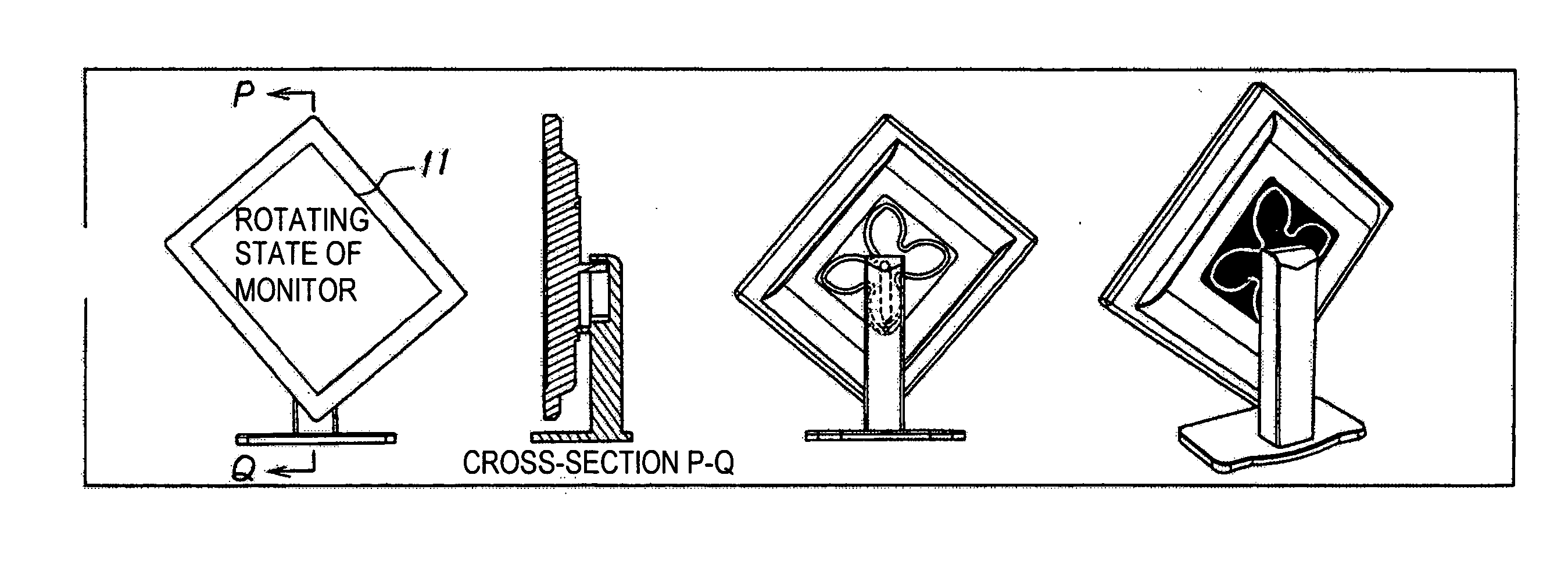
Display device
a technology of display device and screen, which is applied in the direction of machine supports, electric apparatus casings/cabinets/drawers, instruments, etc., can solve the problems of affecting the operation and affecting the display effect of the display device, so as to achieve the effect of optimizing the display height, reducing the labor of the user in changing the screen orientation, and ensuring the balance of the rotation operation
- Summary
- Abstract
- Description
- Claims
- Application Information
AI Technical Summary
Benefits of technology
Problems solved by technology
Method used
Image
Examples
first embodiment
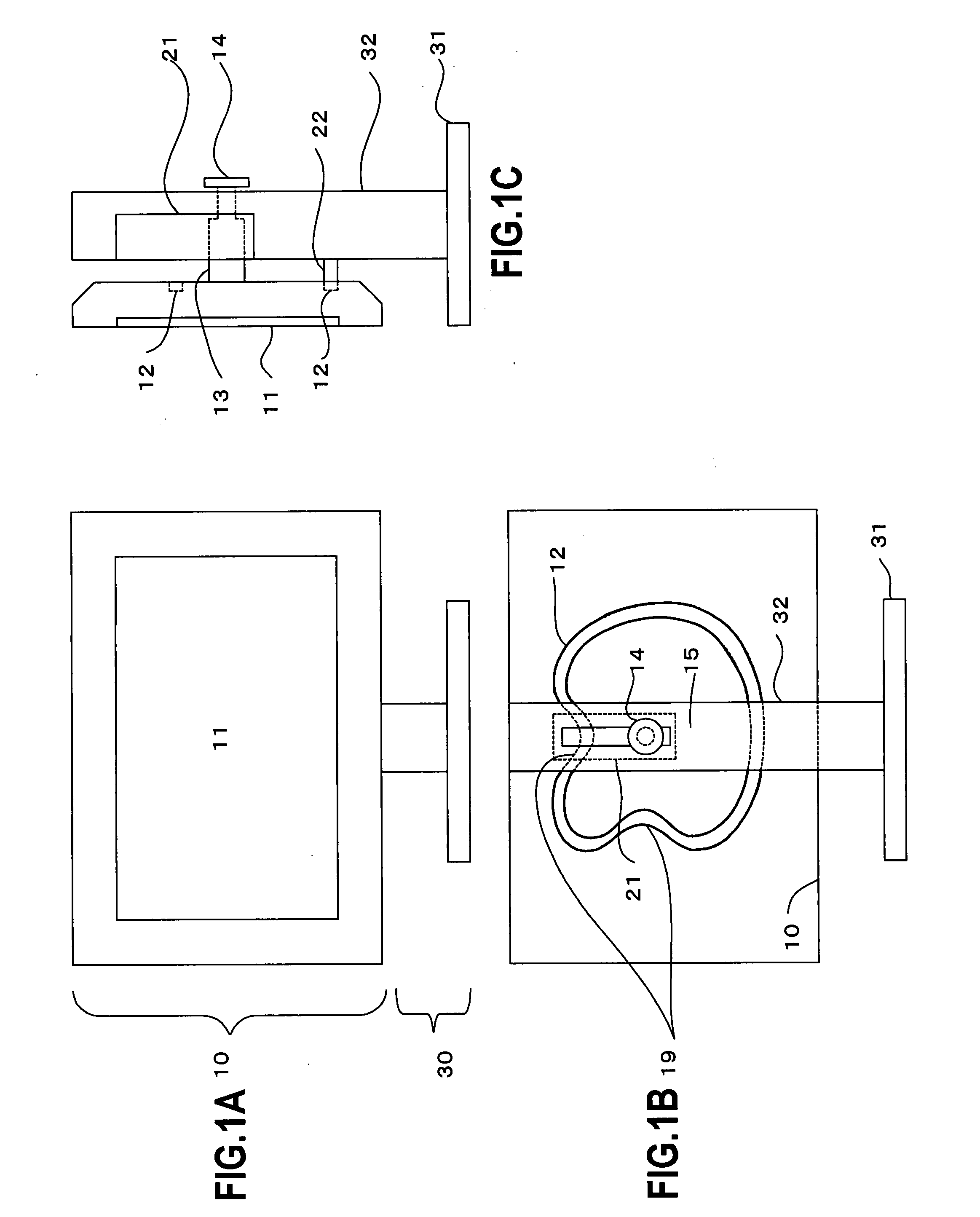
[0030]FIG. 1 illustrates the display device of the present invention. FIG. 1A is a front view of the display device; FIG. 1B is a rear view of the display device; and FIG. 1C is a right-sided view of the display device. The display device is constituted by the display section 10 that comprises a monitor 11, which is a substantially rectangular-shaped display screen that displays information, and stand 30 which supports the display section 10.
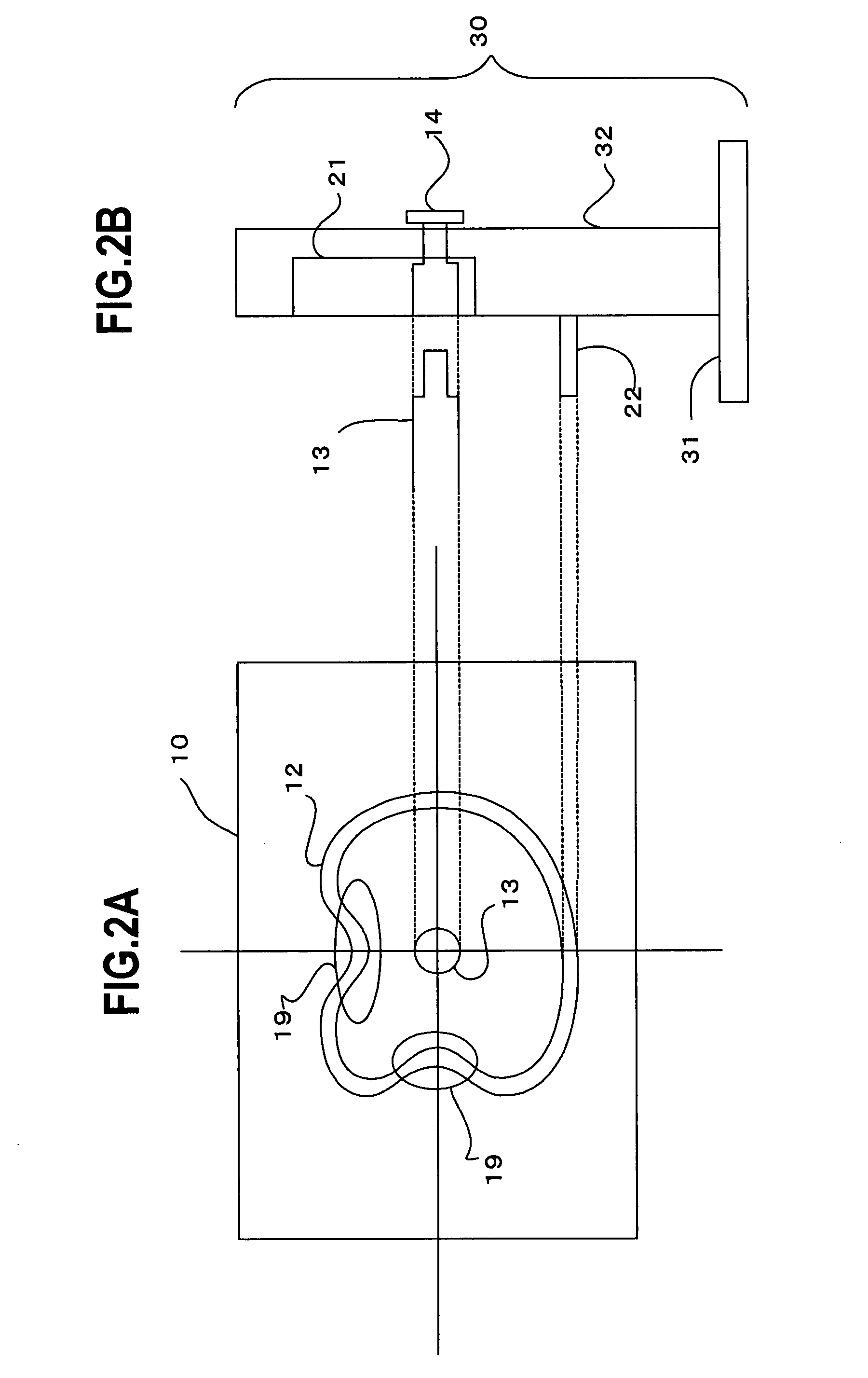
[0031]With reference to FIG. 1B, a cylindrical fixed pin 13 that is perpendicular to the display section 10 is fixed to the display section 10 on the rear face of the display section 10. With reference to FIG. 1C, the fixed pin 13 has a dual-stage structure with a small diameter at a midway point and the tip of the fixed pin 13 penetrates the stand 30 and has abroad fixed member 14 attached thereto. Thus, the display section 10 does not fall forward (left direction in FIG. 1C).
[0032]With reference to FIG. 1C, the rear face of the display section...
second embodiment
[0073]In the display device of the second embodiment, the cam 16 that forms the annular track is provided on the rear face of the display section 10 and the pulley 23 that contacts the cam 16 is provided on the rear face plate 32 of the stand. The pulley 23 is an abutment member that contacts the cam 16 and supports the display section 10. The cam 16 has a predetermined thickness and the outer circumference thereof is followed by the pulley 23. The outer circumference forms an annular track.
[0074]When the display section 10 is rotated, the pulley 23 follows the outer circumference of the cam 16 and the display section 10 is displaced accordingly. This means that, viewed in relative terms, the pulley 23 is guided by the cam 16 and moves along the annular track formed by the outer circumference of the cam 16. Here, because the pulley 23 is fixed to the arm 33, the fixed pin 13 that is fixed to the display section 10 moves along the linear groove 21 in accordance with the distance betw...
PUM
 Abstract
Description
Claims
Application Information
 - R&D
- Intellectual Property
- Life Sciences
- Materials
- Tech Scout
- Unparalleled Data Quality
- Higher Quality Content
- 60% Fewer Hallucinations
Browse by: Latest US Patents, China's latest patents, Technical Efficacy Thesaurus, Application Domain, Technology Topic, Popular Technical Reports.
© 2025 PatSnap. All rights reserved.Legal|Privacy policy|Modern Slavery Act Transparency Statement|Sitemap|About US| Contact US: help@patsnap.com


