Multiple drop weight printhead and methods of fabrication and use

a printhead and drop weight technology, applied in the field of multi-drop weight printheads and methods of fabrication and use, can solve the problems of unknowing the drop volume, particular dispensers, complicated physics behind drop/substrat interaction and nucleation parameters of various fluids

Inactive Publication Date: 2008-03-13
HEWLETT PACKARD DEV CO LP
View PDF24 Cites 16 Cited by
  • Summary
  • Abstract
  • Description
  • Claims
  • Application Information

AI Technical Summary

Problems solved by technology

However, it is often unknown what drop volume will come out of a particular dispenser with a particular fluid (e.g., ethanol, water and toluene will all give different drop volumes from the same physical dispensing geometry).
While it is possible to develop computational models (based on fluid-substrate interaction and drop volume size relative to fundamental fluid properties such as specific heat, heat of vaporization, boiling temperature, etc.) to predict drop volumes, the physics behind drop / substrate interaction and nucleation parameters for various fluids are complicated, and such models can be uncertain and fraught with errors.
Filling multiple dispensers to empirically discover the proper geometry requires a relatively large amount of the fluid and is thus expensive when dealing with high-value fluids.

Method used


Image

  • Multiple drop weight printhead and methods of fabrication and use
  • Multiple drop weight printhead and methods of fabrication and use
  • Multiple drop weight printhead and methods of fabrication and use

Examples


Embodiment Construction

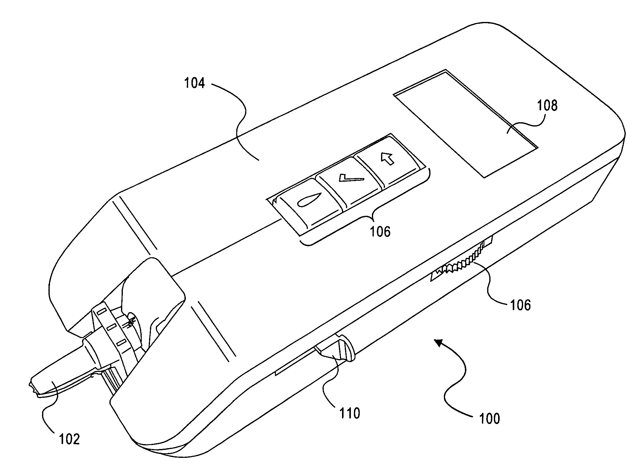
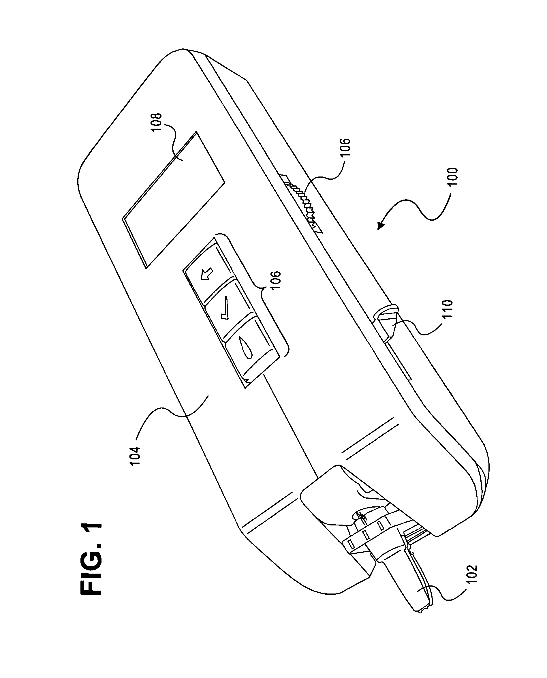
[0008]Referring to the drawings wherein identical reference numerals denote the same elements throughout the various views, FIG. 1 shows a fluid-dispensing device 100, which, by way of example, can be used to accurately dispense small amounts of various fluids in a laboratory setting. The fluid-dispensing device 100 can be used in a handheld manner in that a user can easily hold it in place over a desired location with just one hand while dispensing one or more drops of fluid. Alternatively, the fluid-dispensing device 100 can be mounted to an appropriate positioning means, such as an X-Y carriage, for positioning the fluid-dispensing device 100 in a desired location. The fluid-dispensing device 100 can also be mounted to stationary objects.

[0009]The fluid-dispensing device 100 includes a disposable, interchangeable pen 102, from which one or more drops of fluid are ejected, and an enclosure 104, which supports the pen 102 and is the part of the device 100 that is handheld and / or mo...


PUM


Abstract

A printhead includes a chamber layer and at least two orifice layers. A first orifice layer is disposed on the chamber layer, and a second orifice layer is disposed on the first orifice layer. The second orifice layer has at least one counterbore formed therein. A first nozzle is formed through both orifice layers and produces droplets of a first drop weight. A second nozzle is formed through the first orifice layer, coincident with the counterbore, and produces droplets of a second drop weight that is different than the first drop weight. In one embodiment, the printhead is used in a stand-alone fluid-dispensing device.

Description

BACKGROUND OF THE INVENTION[0001]Drop-on-demand and continuous jetting technologies have been used for many years to jet colorant onto various substrates for the purposes of printing documents, labels, digital photographs and the like. Inkjet printing technology is commonly used in many commercial products such as computer printers, graphics plotters, copiers, and facsimile machines. The small drops of fluid that can be achieved with inkjet technology make the technology desirable for other applications as well. Recently, there has been interest in using jetting technologies for the precision dispensing of high value materials. For example, inkjet technology could be used to dispense reagents, enzymes or other proteins into well-plates for the purpose of fluid mixing or initiating chemical reactions. Other examples of alternative applications include the printing of LCD color filters and transistor back-planes.[0002]In a laboratory environment, it is useful to be able to accurately ...

Claims


Application Information

Patent Timeline
Patent Type & Authority Applications(United States)
IPC IPC(8): B41J3/36B01L99/00
CPCB01L3/0268B01L2200/14B01L2300/027B41J2/1404B41J2002/14475B41J2/162B41J2/1631B41J2/2125B41J3/36B41J2/1433
Inventor NIELSEN, JEFFREY A.OLBRICH, CRAIG A.
Owner HEWLETT PACKARD DEV CO LP
Why Eureka
Try Eureka