
Bad video edit detection

a technology of editing detection and bad video, applied in the field of digital video signal processing, can solve problems such as poor conversion performance, twitter effect, and not a straightforward linear upsampling problem

Inactive Publication Date: 2008-03-13
TEXAS INSTR INC
View PDF5 Cites 15 Cited by
  • Summary
  • Abstract
  • Description
  • Claims
  • Application Information

AI Technical Summary

Problems solved by technology

However, when displaying video on a display that can support a high enough refresh rate so that flicker is not perceivable, progressive scanning is more preferable, since interlacing reduces the vertical display resolution and causes twitter effects for displaying pictures with high vertical frequency.
This is not a straightforward linear upsampling problem, however, since TV signals do not fulfill the sampling theorem constraints (vertical prefiltering usually is not employed when the sensors in the camera sample the scene).
Generally speaking, spatial (intra-frame), temporal (inter-frame), and spatial-temporal de-interlacing algorithms are simple and usually lead to poor conversion performance.
Motion adaptive techniques are generally advantageous but of much higher complexity in implementation.
Nevertheless, neither of these techniques can fully recover the lost information caused during interlacing because interlacing is a non-reversible procedure.
It is not quite true, however, due to a few challenges as set forth below.
In addition, if the video is decoded and transmitted to the receiver through an analog channel, the introduced transmission noise will make these two fields quite different.
All these possibilities bring difficulties in identifying the two fields that are supposed to be the same in theory.
(5) During video editing, film can be concatenated with any other source such as a video source or another film source, which may cause the original cadence to break.
Errors occur during transition from one source to another source if the same cadence is still used for re-interleaving.
These errors will show up as artifacts on screen.
As these implementations solely rely on the detected cadence of field differences, they are incapable of handling the aforementioned challenges such as mixed content and bad edit, even though they usually can handle pure and clean 3-2 pull down source very well.

Method used


Image

  • Bad video edit detection
  • Bad video edit detection
  • Bad video edit detection

Examples


Embodiment Construction

1. Overview

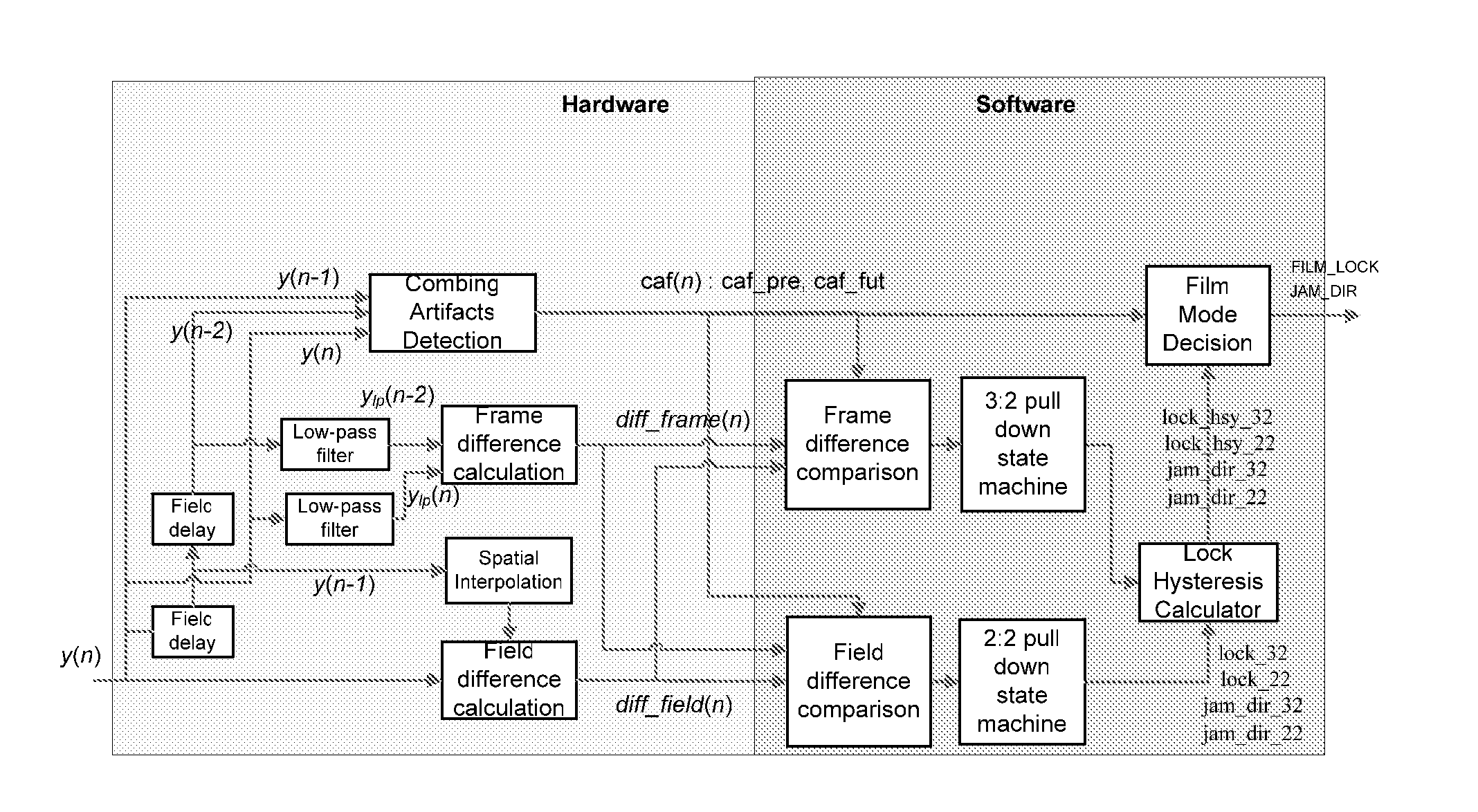
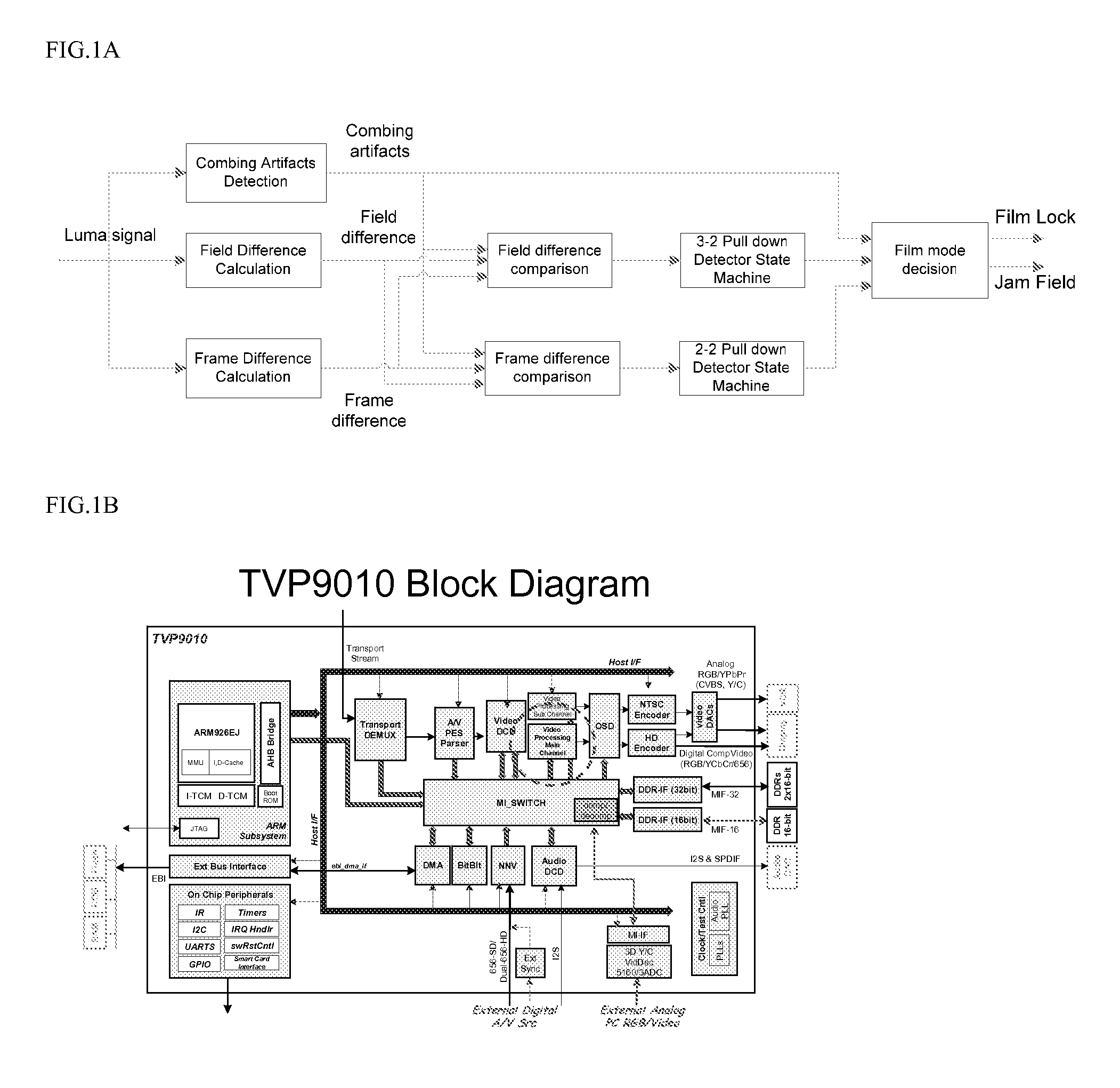
[0038]Preferred embodiment methods perform film mode detection with pull down detection which incorporates combing artifact measures. Further preferred embodiments provide bad edit and mixed content detection when only a two-field memory is available by accumulation of partial field combing artifact measures. FIGS. 1, 3, and 6 illustrate preferred embodiment film mode detectors implementing preferred embodiment methods.

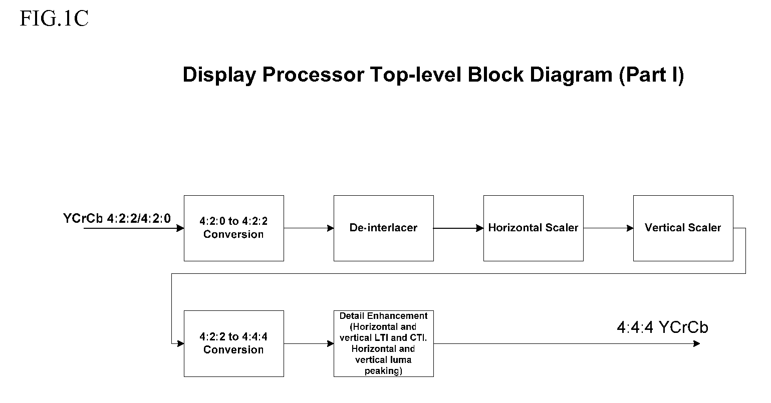
[0039]Preferred embodiment systems perform preferred embodiment methods with any of several types of hardware: digital signal processors (DSPs), general purpose programmable processors, application specific circuits, or systems on a chip (SoC) such as combinations of a DSP and a RISC processor together with various specialized programmable accelerators. FIG. 1B illustrates functional blocks of a processor with FIGS. 1C showing details of the display processing, including de-interleaving. A stored program in an onboard or external (flash EEP)ROM or FRAM coul...


PUM


Abstract

Film mode detection with bad edit detection used in de-interlacing video includes use of combing artifact detection in both 3-2 pull down detection and 2-2 pull down detection. Further, combing artifact detection uses only two field memories by accumulation of partial field statistics for comparisons.

Description

CROSS-REFERENCE TO RELATED APPLICATIONS[0001]This application claims priority from and incorporates by reference provisional applications Nos. 60 / 824,875 and 60 / 824,878, both filed Sep. 7, 2006. The following co-assigned copending patent applications disclose related subject matter: applicaiton Ser. Nos. 11 / 550,100, filed 10 / 17 / 2006 and co-filed TI-62582 [Zhai+Chang].BACKGROUND[0002]The present invention relates to digital video signal processing, and more particularly to film mode and bad edit detection as is useful in de-interlacing video fields.[0003]For moving picture systems, interlaced video format is widely used to reduce data rate. That is, each image frame consists of two fields, each of which contains samples of either the even numbered (top field) or the odd numbered (bottom field) lines of the image. In interlaced scan, fields are scanned and displayed sequentially, as shown for a 5×5 pixel portion in FIG. 7A. By taking advantage of the time it takes for an image to fade...

Claims


Application Information

Patent Timeline
Patent Type & Authority Applications(United States)
IPC IPC(8): H04N7/01
CPCH04N7/0112H04N11/20H04N9/64H04N7/012
Inventor ZHAI, FANCHANG, WEIDER PETER
Owner TEXAS INSTR INC
Learn More