Optical barrel enclosing rod lenses

a technology of optical barrels and lenses, applied in the field of optical barrels, can solve the problems of laborious manufacture and difficult assembly, and achieve the effect of convenient lens rod installation and manufactur

Active Publication Date: 2008-03-13
OLYMPUS WINTER & IBE
View PDF4 Cites 10 Cited by
  • Summary
  • Abstract
  • Description
  • Claims
  • Application Information

AI Technical Summary

Benefits of technology

[0007]The objective of the present invention is to create a system of the above kind which shall be manufactured more easily and allows easier lens rod installation.

Problems solved by technology

These known designs of the field being discussed entail elaborate manufacture and difficult assembly.

Method used


Image

  • Optical barrel enclosing rod lenses
  • Optical barrel enclosing rod lenses
  • Optical barrel enclosing rod lenses

Examples


Embodiment Construction

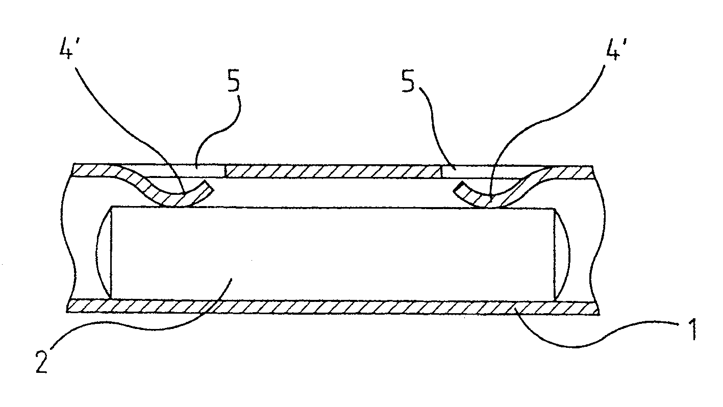
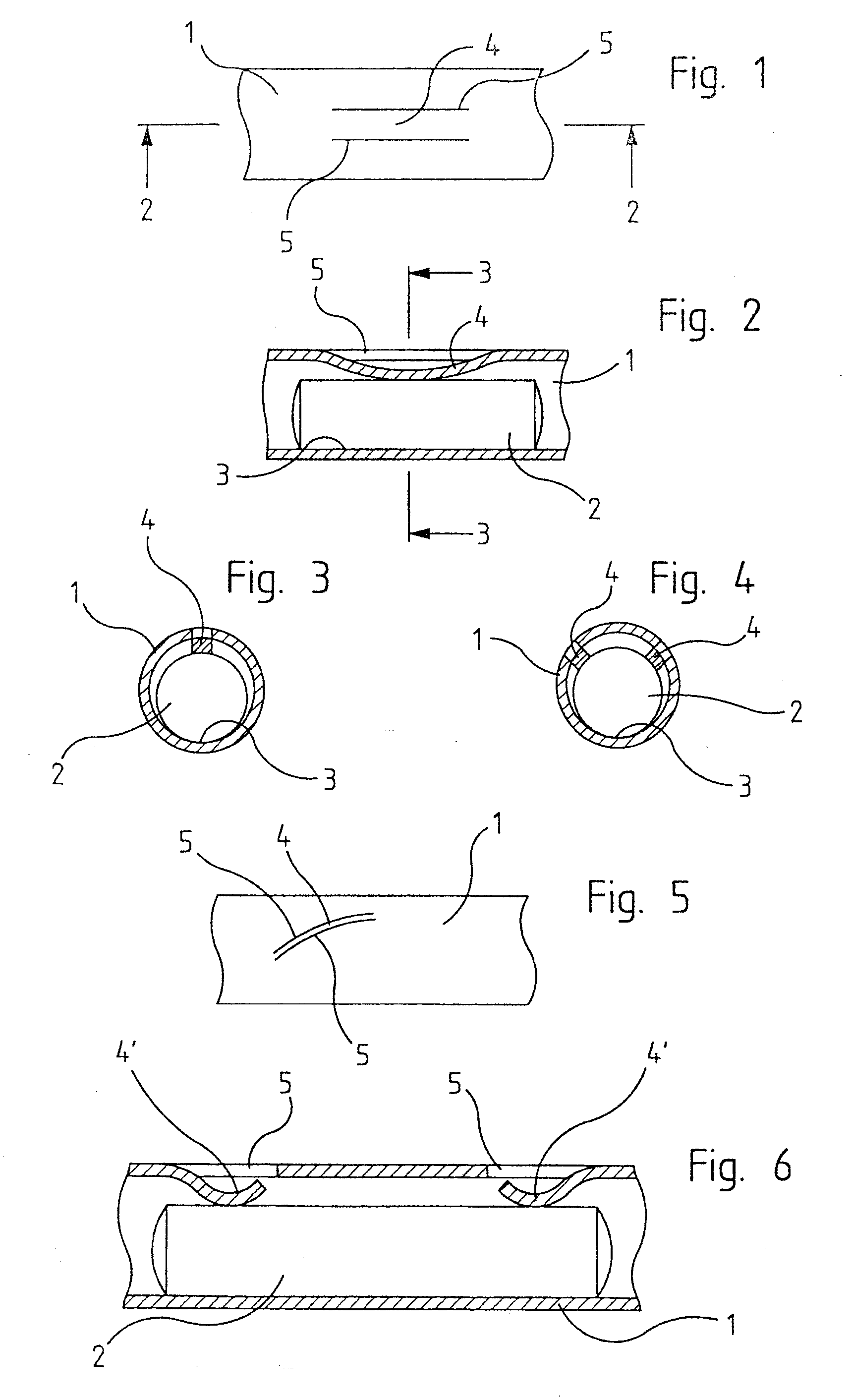
[0024]FIGS. 1-3 display a first embodiment mode of a barrel 1 of which only a small portion is shown, that for clarity shows an exaggerated play between the barrel 1 and an enclosed rod lens 2. This rod lens makes line-contact with the barrel 1 at the site 3, being kept in place at the opposite circumferential site by a blade 4 which is able to freely move inward between two cutouts 5 and illustratively is forced downward using an appropriate tool until making contact with the rod lens 2. For this purpose the material of the barrel 1 may be one retaining its new shape once deformed.

[0025]However, in a preferred embodiment of the present invention, the barrel is made of a spring material such as an appropriately elastic steel. The blade 4 is pre-shaped inward somewhat farther than indicated in FIGS. 2 and 3 and thereby may yield resiliently when the lens rod 2 is axially inserted as far as the shown assembly position.

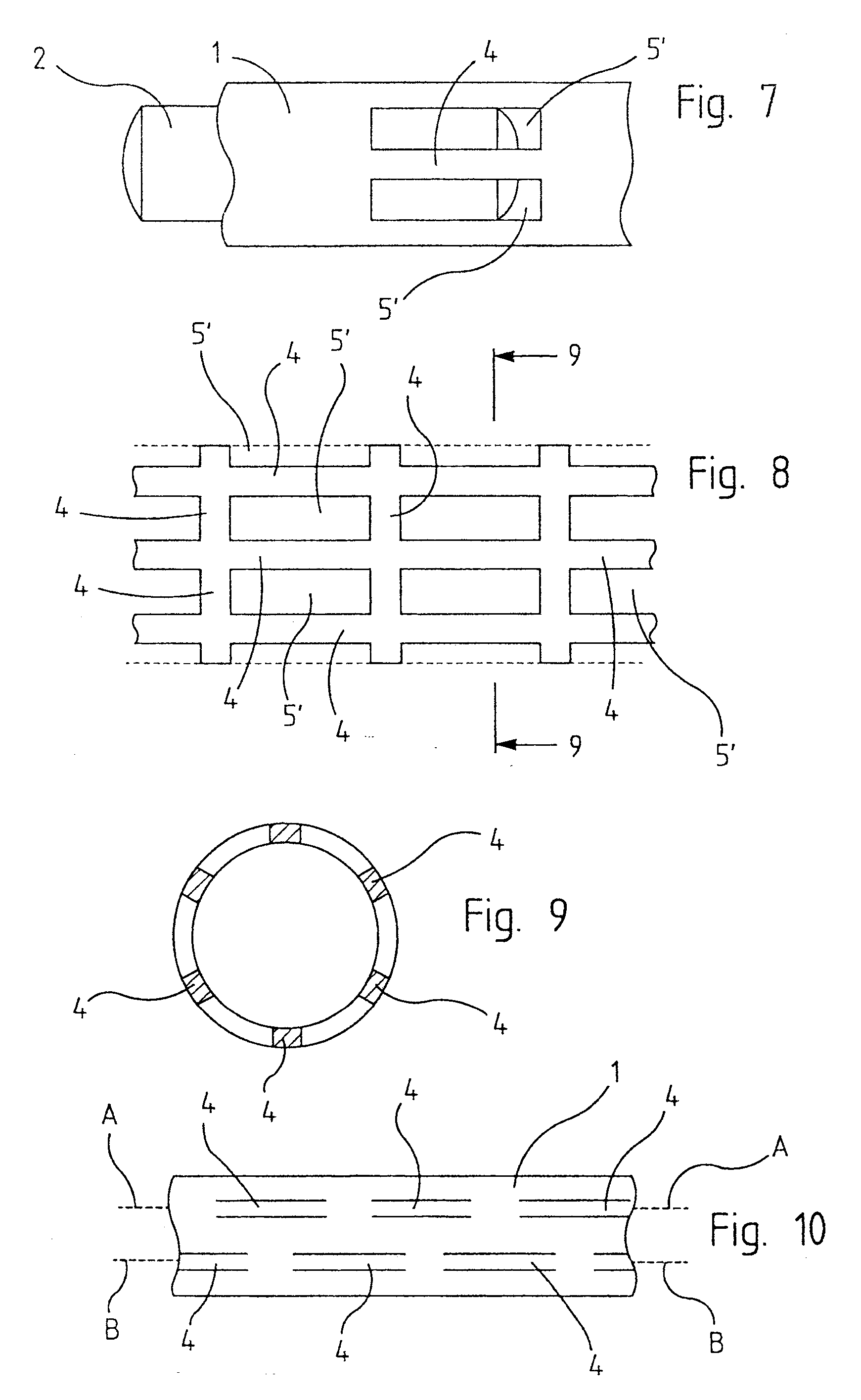
[0026]To attain a three-point rest as seen in cross-section, two bl...


PUM


Abstract

An optical barrel (1) enclosing rod lenses (2) of a rigid endoscope optics, the rod lenses being contacted by the barrel in zones wherein an inwardly deforming, blade (4, 4′) cut free by two associated cutouts (5, 5′) in the barrel (1) is designed at each zone to make contact with rod lens (2).

Description

BACKGROUND OF THE INVENTION[0001]The present invention relates to an optical barrel, hereafter barrel, of the kind enclosing rod lenses of a rigid endoscope optics.[0002]Rod lenses in endoscope optics serve as a relay system to transmit the image from a distal objective to a proximal ocular. A number of rod lenses are configured in a row and apart from each other. The endoscope optics is enclosed by a hermetically sealing cladding tube and includes a barrel within the cladding tube to keep the rod lenses accurately in place. The rod lenses must be sufficiently fixed in place within the barrel not to change their positions even when impacted in order to assure reproducible image transmission. The rod lens dimensions must be commensurately smaller than the barrel to allow axially displacing the lenses when the optical barrel is being assembled and, moreover, to preclude that slightly flexing the barrel should entail rod lens destruction.[0003]To that end the rod lenses are only partly...

Claims


Application Information

Patent Timeline
Patent Type & Authority Applications(United States)
IPC IPC(8): G02B7/02
CPCG02B7/02A61B1/002G02B23/243
Inventor SCHOLER, UWE
Owner OLYMPUS WINTER & IBE
Why Eureka
Try Eureka