Undercut fillet radius for blade dovetails

a technology of blade dovetails and undercutting, which is applied in the field of undercutting fillet radius for blade dovetails, can solve the problems of having a negative effect on the design stress parameters of the p-cut section

Active Publication Date: 2008-03-13
GENERAL ELECTRIC CO
View PDF11 Cites 40 Cited by
  • Summary
  • Abstract
  • Description
  • Claims
  • Application Information

AI Technical Summary

Problems solved by technology

The prior undercut radius concept did not accommodate this unique stress profile

Method used


Image

  • Undercut fillet radius for blade dovetails
  • Undercut fillet radius for blade dovetails
  • Undercut fillet radius for blade dovetails

Examples


Embodiment Construction

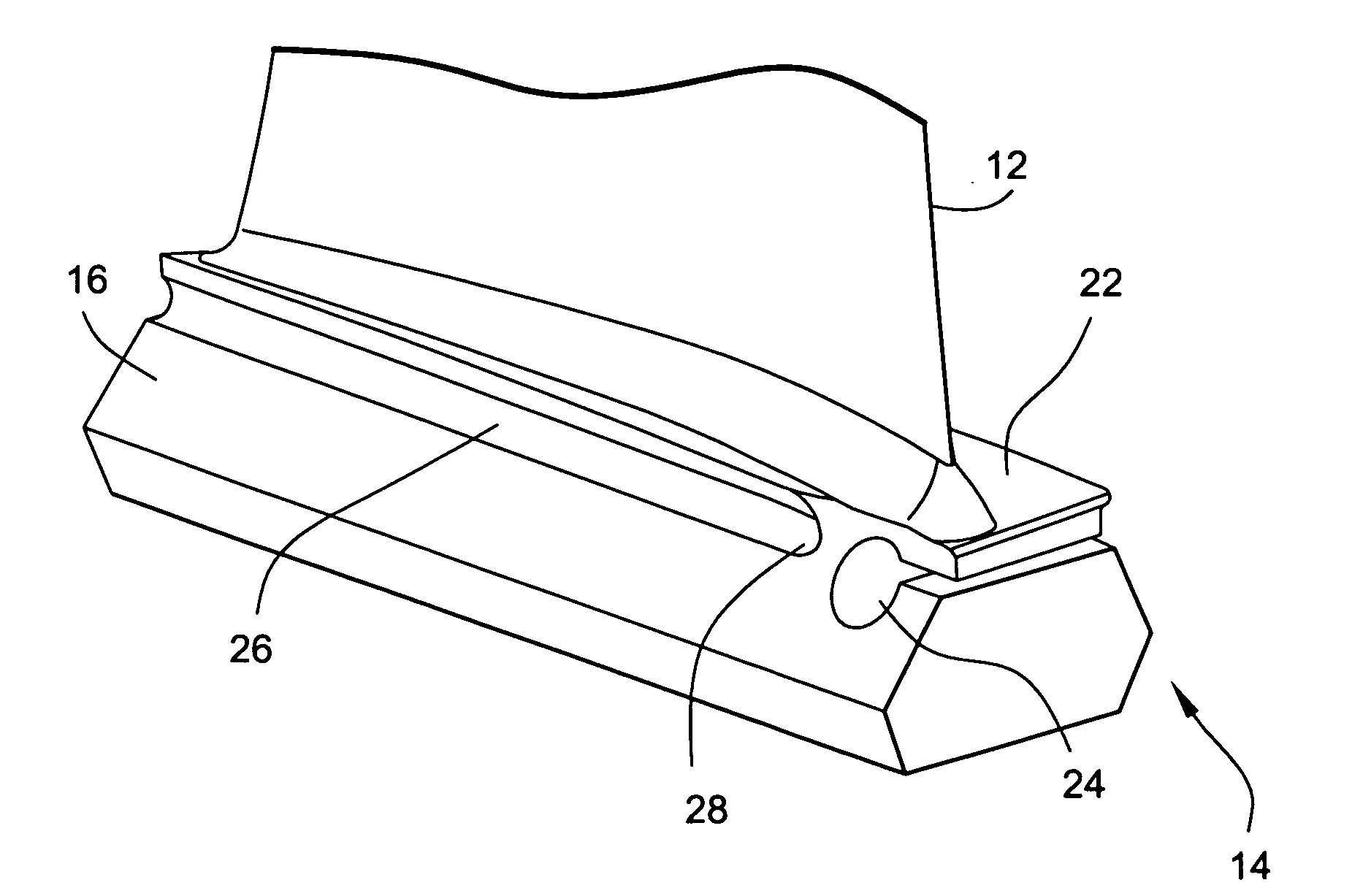
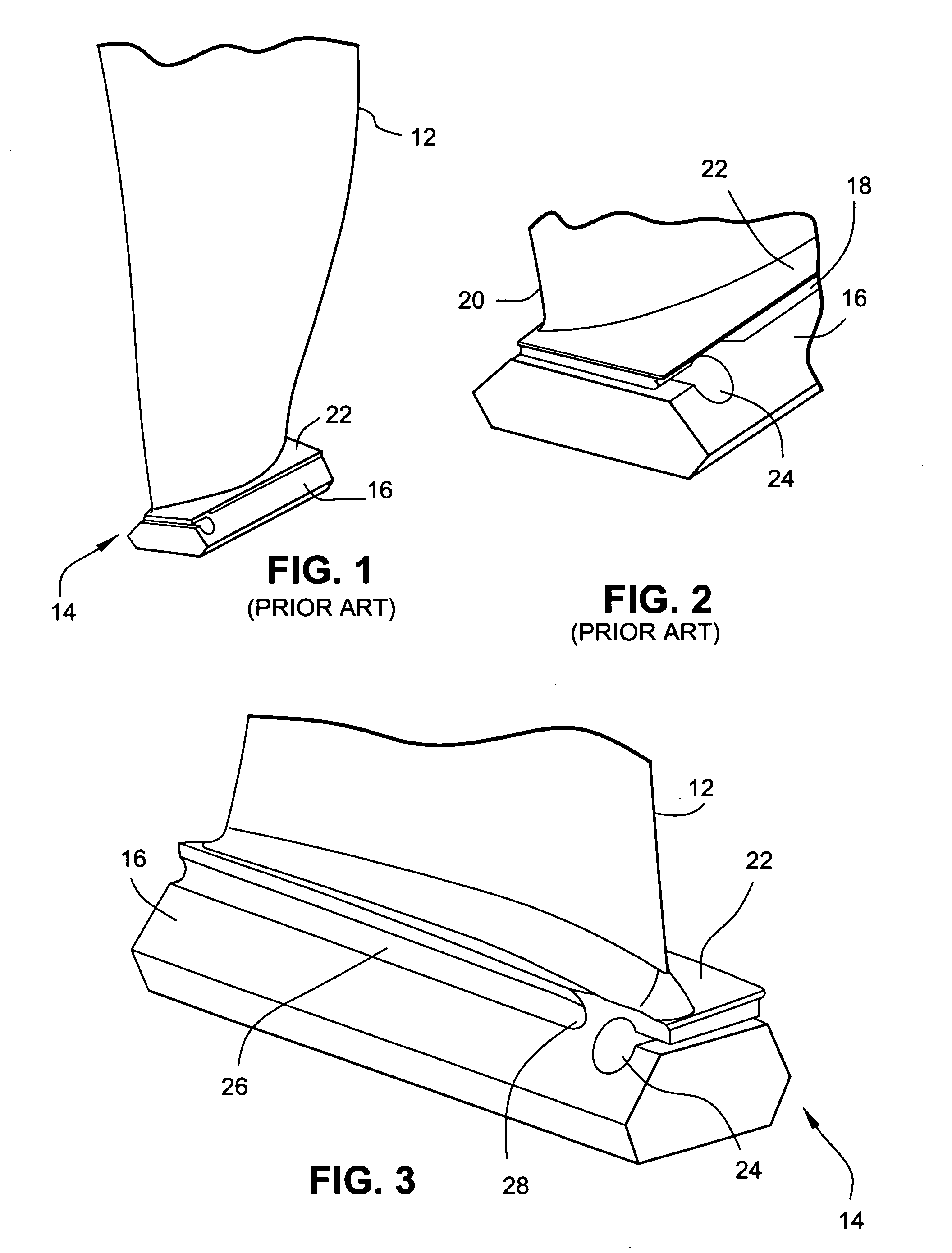
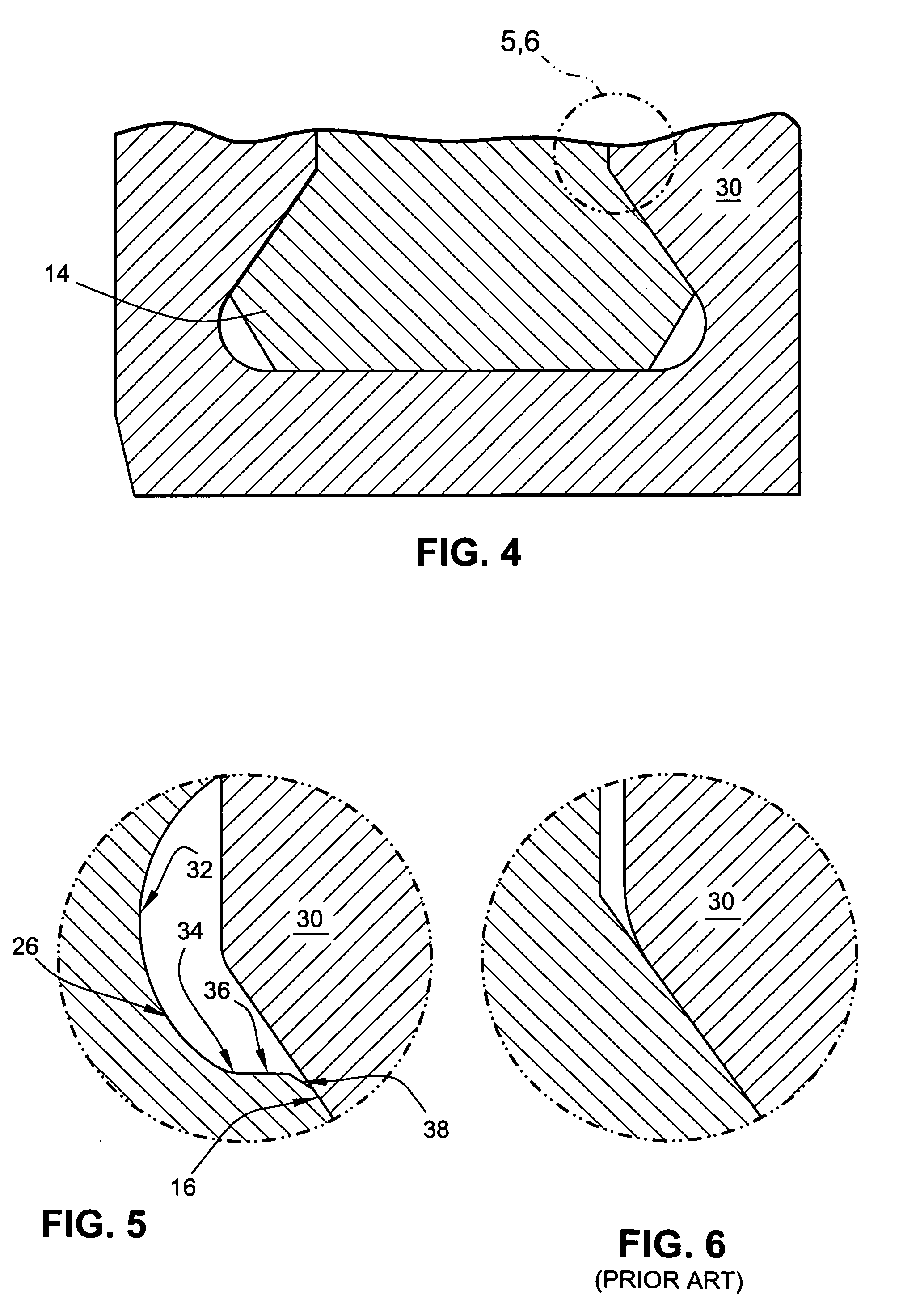
[0014]FIG. 3 is a perspective view of a turbine or compressor blade assembly including a modified dovetail section. The blade assembly includes a blade 12 (airfoil portion), a dovetail platform 22, and an attachment or root portion (dovetail section) 14 that typically is formed with a dovetail configuration, which enables the blade assembly to be loaded onto a compressor wheel or rotor 30 (see FIGS. 4-6).

[0015]A P-cut 24 relief slot is formed at the forward end of the dovetail section 14. This feature reduces the airfoil leading edge stresses making the blade less susceptible to damage on the leading edge.

[0016]Material is removed from and along the front face of the dovetail pressure surface 16 to form an undercut fillet radius 26 at an intersection of the dovetail platform 22 and the dovetail pressure surface 16. The undercut radius 26 extends toward a forward end of the dovetail 14, wherein an axial location of the undercut fillet radius termination is defined a predetermined dis...


PUM


Abstract

A turbine or compressor blade assembly includes a blade fixed to a dovetail section attachable to a wheel. The dovetail section has a dovetail shaped to fit in a correspondingly shaped slot in the wheel. A dovetail platform serves as an interface between the blade and the dovetail. An undercut fillet radius is formed at an intersection of the dovetail platform and a dovetail pressure surface, where the undercut radius has a multi-part profile shape configured to attenuate edge of contact stresses. An additional feature is the area where the undercut radius transitions into the P-cut area at the forward end (leading edge) of the dovetail.

Description

BACKGROUND OF THE INVENTION[0001]The invention relates to stress reduction in the interface between a blade dovetail and a wheel slot and, more particularly, to a dovetail section including an undercut fillet radius having a multi-part profile shape formed at an intersection of the dovetail platform and a dovetail pressure surface.[0002]FIGS. 1 and 2 show a conventional compressor blade assembly including a blade 12 fixed to a dovetail section 14, which is attachable to a compressor wheel (not shown). An analysis of a failed blade shows that the failure resulted from fretting on the dovetail pressure surfaces 16 near the small fillet radius 18 that transitions from the blade neck 20 to the dovetail platform 22. The analysis showed the stress in the small 0.022 fillet radius 18 was substantial enough to grow micro-cracks in the fretted area eventually causing ultimate failure (blade liberation). A subsequent review of several hundred parts showed fretting was prevalent in these areas...

Claims


Application Information

Patent Timeline
IPC IPC(8): F01D11/00
CPCF01D5/147F01D5/3007F05D2250/70F05D2240/80F05D2260/94F01D5/00F01D5/14F01D5/30F01D25/00
Inventor MILLER, WILLIAM JOHNBUSBEY, BRUCE C.DIXON, WILLIAM E.NAPARTY, LYNN M.
Owner GENERAL ELECTRIC CO
Why Eureka
Try Eureka