Method and apparatus of multi-modality image fusion

a multi-modality, image-fusion technology, applied in the field of diagnostic imaging, can solve the problems of not being able to replace existing pet and ct systems with combined imagers, not being able to achieve the effect of a diagnostic imaging center, hospital, or the lik

Active Publication Date: 2008-03-13
GENERAL ELECTRIC CO
View PDF6 Cites 20 Cited by
  • Summary
  • Abstract
  • Description
  • Claims
  • Application Information

AI Technical Summary

Problems solved by technology

Fusion of functional and anatomical data that has been acquired separately with imaging systems predicated on different imaging technologies can be problematic.
A combined PET / CT scanner, however, may not be feasible in all circumstances.
For instance, it may not be practical for a diagnostic imaging center, hospital, or the like to replace existing PET and CT systems with a combined imager.
However, the scanner cannot provide a composite image of PET and MR data, SPECT and MR data, or SPECT and CT data.
As such, a hybrid system may not address the myriad of diagnostic needs required of a radiologist or other health care provider in rendering a diagnosis to a patient.
Another solution that is consistent with conventional fusion techniques fails to adequately address the drawbacks associated with the overlaying of collocated functional and anatomical data that are not registered.
That is, present fusion protocols combine data having a common coordinate alignment, but fail to register the functional and anatomical images.
In this regard, conventional fusion techniques orientate the functional and anatomical data but do not take measures to sufficiently align the functional and anatomical data.
Furthermore, the image resolution from PET and SPECT are limited by maximum energy resolution of positron-emitting isotopes.
The resolution of functional images compared to anatomical images is notably inferior.
As a result, the radiologist or other health care provider must decipher a single composite image with the functional and anatomical information, with respect to one another, being misaligned.
However, the respective images from which the composite image is formed are not registered because the coordinate systems are not common to both image sets.
However, these automated methods do not use any localized anatomical constraints to guide them.
As a result, these conventional approaches may only perform data-to-data fusion and, as such, are inapplicable when fusion between data and modeled data, or fusion between modeled data and modeled data is desired.

Method used


Image

  • Method and apparatus of multi-modality image fusion
  • Method and apparatus of multi-modality image fusion
  • Method and apparatus of multi-modality image fusion

Examples


Embodiment Construction

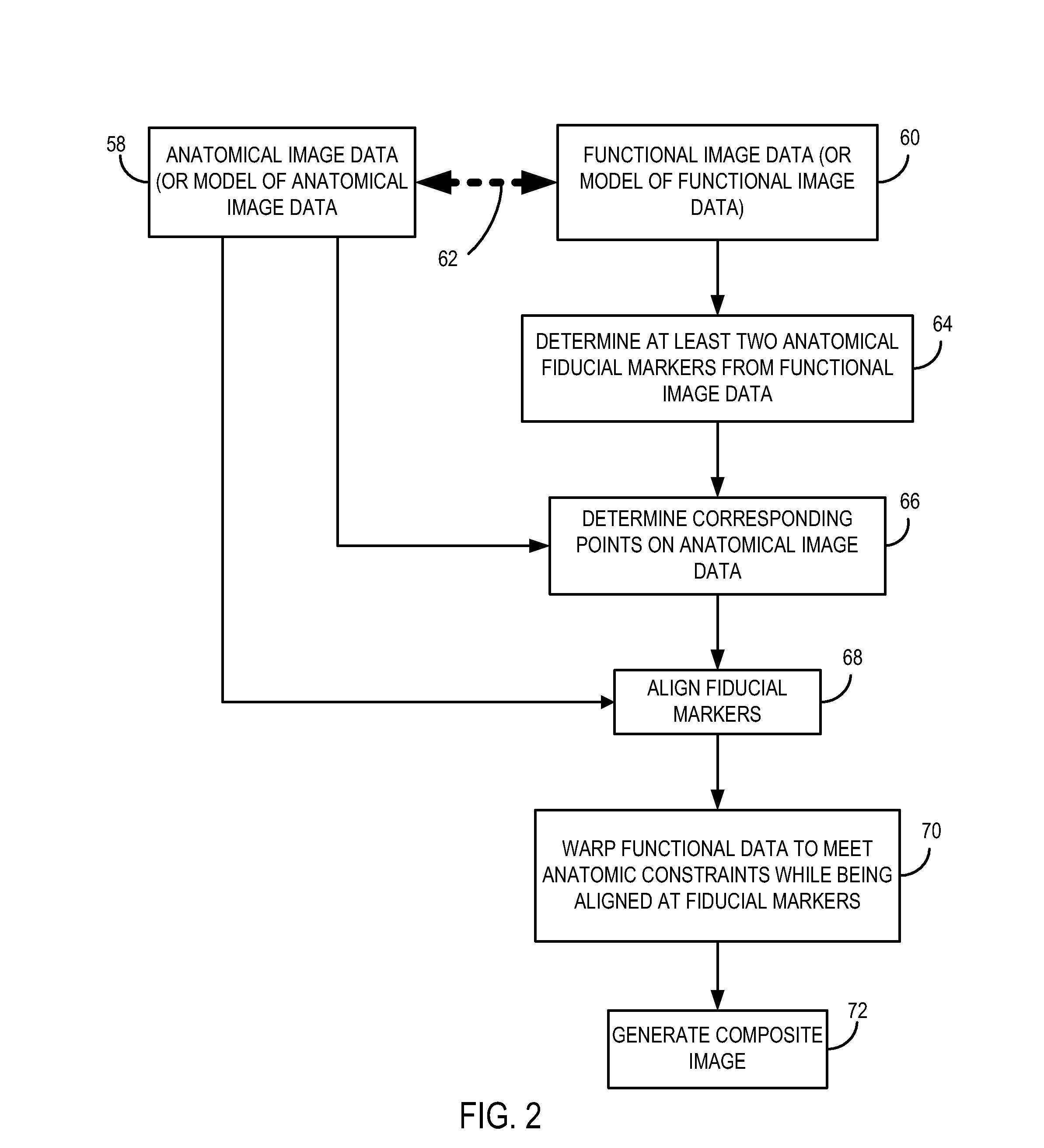
[0019] The present invention will be described with respect to a process, which may be carried out through interaction with a user or automatically, to generate a composite diagnostic image of functional and anatomical data acquired separately with a PET imaging system and a CT imaging system. One skilled in the art will appreciate, however, that imaging systems of other modalities such as MR, SPECT, ultrasound, x-ray, and the like may be used to acquire the functional and anatomical data to be combined into a composite image. Further, the present invention will be described with respect to the acquisition and imaging of data from a cardiac region of a patient. However, one skilled in the art will appreciate that the present invention is equivalently applicable with data acquisition and imaging of other anatomical regions of a patient.

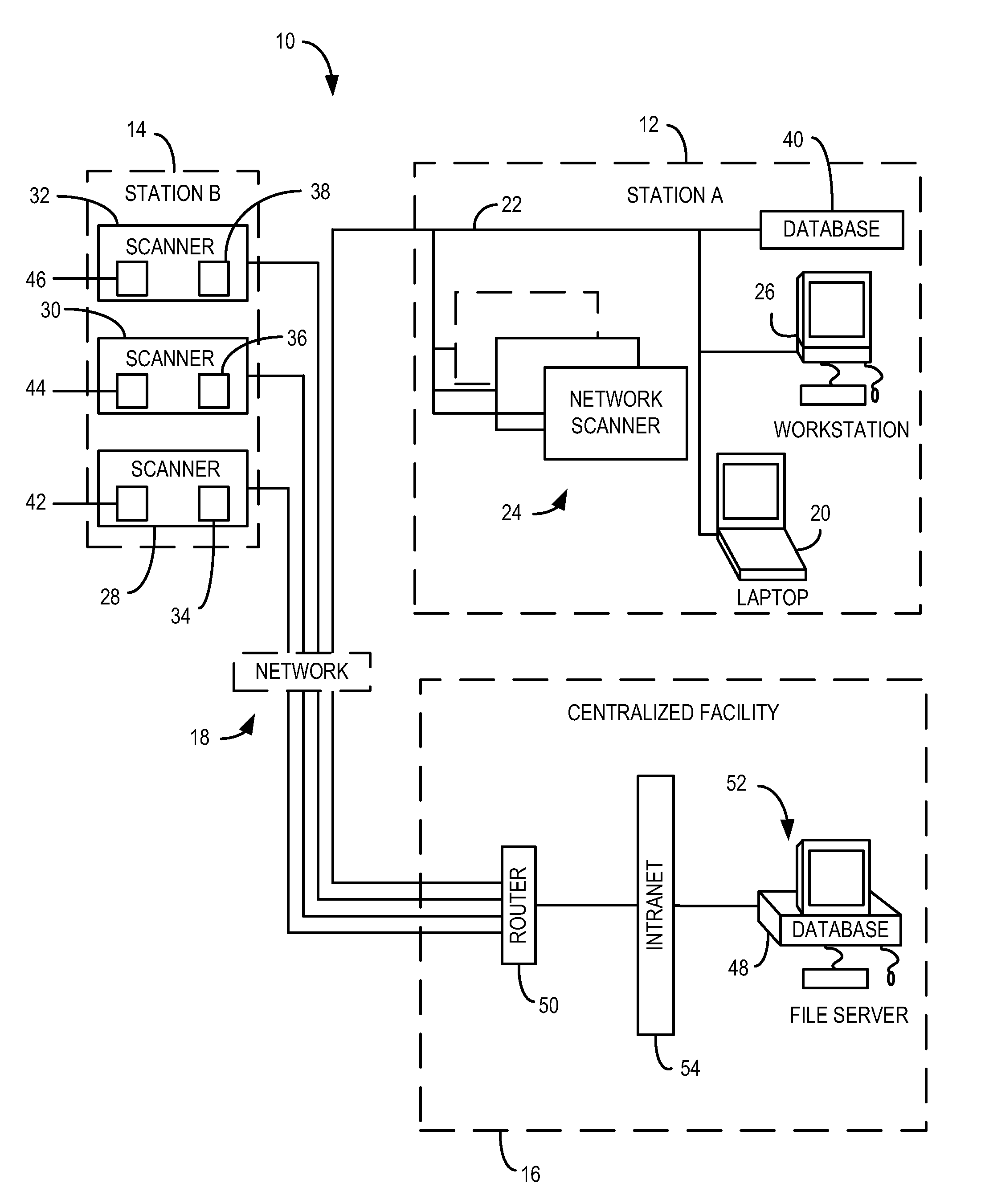
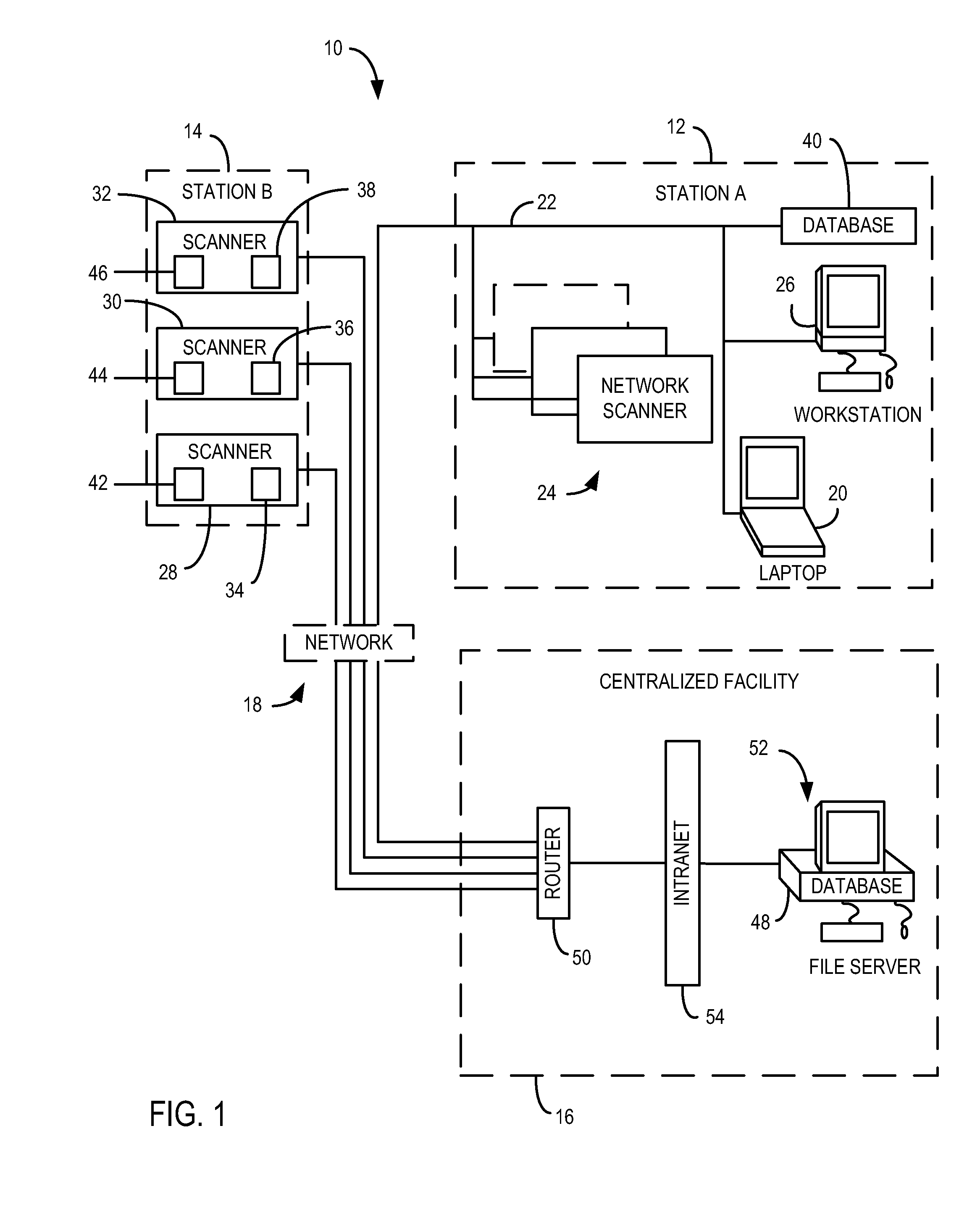
[0020] Referring now to FIG. 1, an overview block diagram of a medical diagnostic and service networked system 10 is shown which includes a plurality...


PUM


Abstract

The present invention is directed to a method and apparatus for fusing or combining functional image data and anatomical image data. The invention, which may be carried out through user interaction or automatically, enables composite and clinically valuable images to be generated that display functional and anatomical data acquired with different imaging systems. By identifying fiducial markers on a functional data image and correlating the fiducial markers with anatomical markers or indicia on the anatomical data image, the respective images may be aligned with one another before a composite image is generated.

Description

CROSS-REFERENCE TO RELATED APPLICATION [0001] The present application is a continuation of and claims priority of U.S. Ser. No. 10 / 604,673 filed Aug. 8, 2003, the disclosure of which is incorporated herein by reference.BACKGROUND OF THE INVENTION [0002] The present invention relates generally to diagnostic imaging and, more particularly, to a method and apparatus of combining or fusing functional diagnostic data and anatomical diagnostic data acquired of a subject with imaging systems of different modalities to generate a composite image for clinical inspection. [0003] The fusion of functional image data and anatomical image data is a widely-practiced technique to provide composite images for improved pathology identification and clinical diagnosis. Typically, the functional and anatomical image data is acquired using nuclear medicine based systems such as single-photon computed tomography (SPECT), and positron emission tomography (PET) or radiology based imaging systems such as com...

Claims


Application Information

Patent Timeline
Patent Type & Authority Applications(United States)
IPC IPC(8): A61B5/05G06K9/36G06K9/00G06K9/32G06T7/00
CPCG06T7/0038G06T7/0028G06T7/33G06T7/38
Inventor HERTEL, SARAH R.AVINASH, GOPAL B.
Owner GENERAL ELECTRIC CO
Why Eureka
Try Eureka