
Tissue morcellating device

a morcellating device and tissue technology, applied in the field of tissue morcellation devices, can solve the problems of morcellation of tissue, stalling of the morcellating device, and increasing the complexity of the instrument, and achieve the effect of increasing the size of the apertur

Inactive Publication Date: 2008-03-13
GYRUS MEDICAL LTD
View PDF41 Cites 23 Cited by
  • Summary
  • Abstract
  • Description
  • Claims
  • Application Information

AI Technical Summary

Benefits of technology

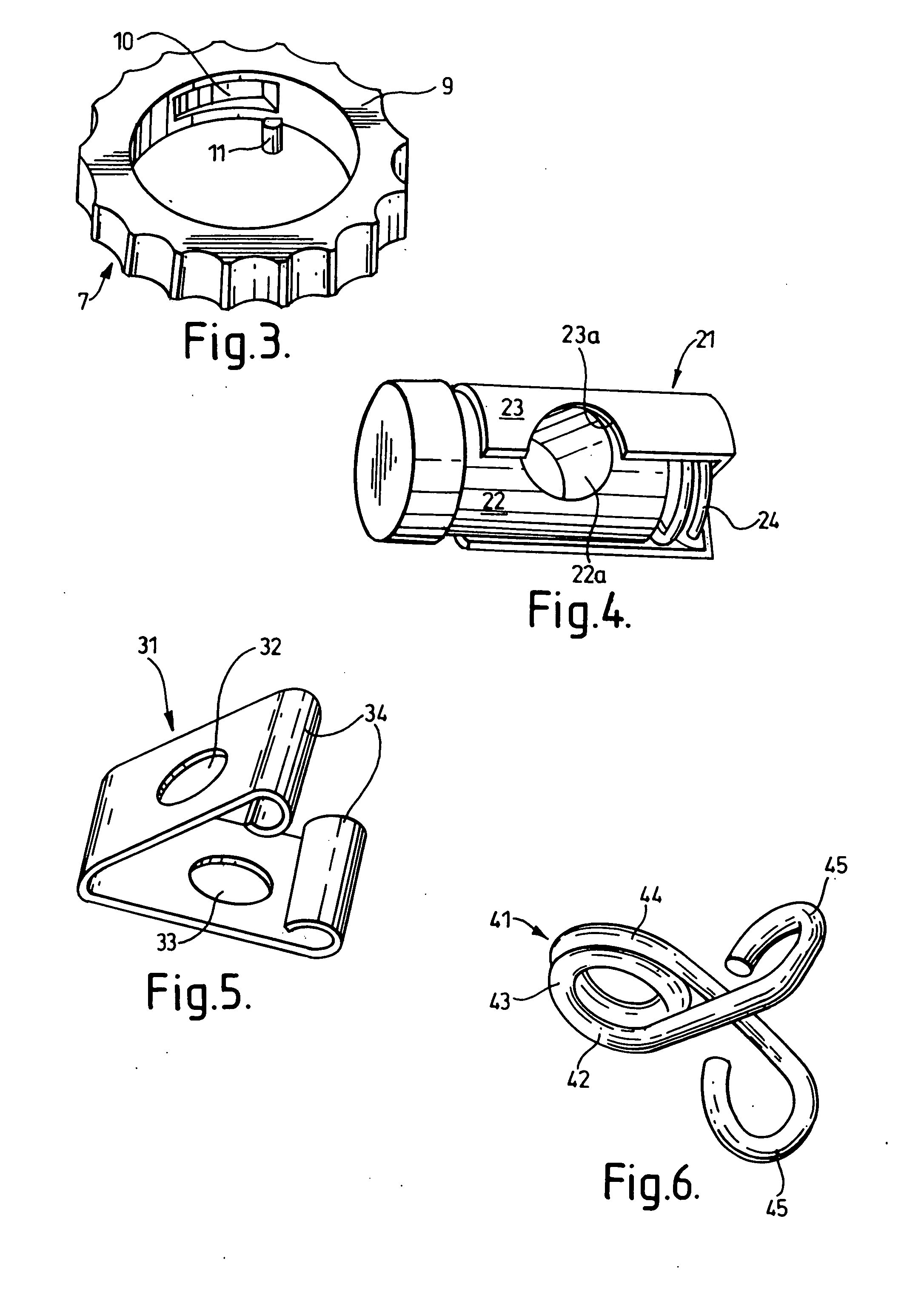
[0010]In yet another preferred embodiment, the stop is constituted by a V-shaped member made of resilient material, each arm of the V-shaped member being provided with an aperture whose diameter is greater than that of the tube, the free ends if the arms of the V-shaped member being manually engageable to move the free ends towards one another against the resilience of the V-shaped member, the arrangement being such that, in a first configuration in which no pressure is applied to the manually-engageable portions, the apertures in the V-shaped arms are sufficiently out of alignment for frictional engagement with the tube when the tube is positioned therethrough, thereby to fix the stop to the tube in a predetermined position therealong; and, in a second configuration, in which the manually-engageable portions are pressed together, the apertures are aligned to permit the stop to be moved freely along the tube.

Problems solved by technology

This rotation of the electrode necessitates a mechanical drive arrangement, which increases the complexity of the instrument.
One problem with this known arrangement is that the morcellating device can be inserted too far into a patient's body, and this can lead to the morcellation of tissue which is not required to be morcellated.
It can also lead to stalling of the morcellating device as it tries to morcellate too much tissue.

Method used


Image

  • Tissue morcellating device
  • Tissue morcellating device
  • Tissue morcellating device

Examples


Embodiment Construction

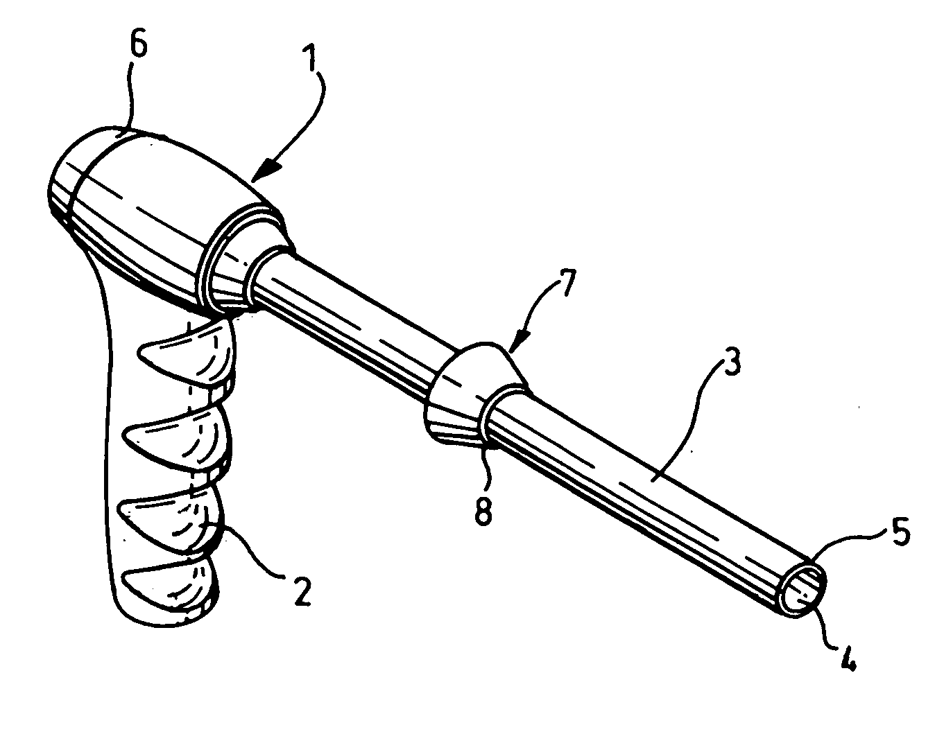
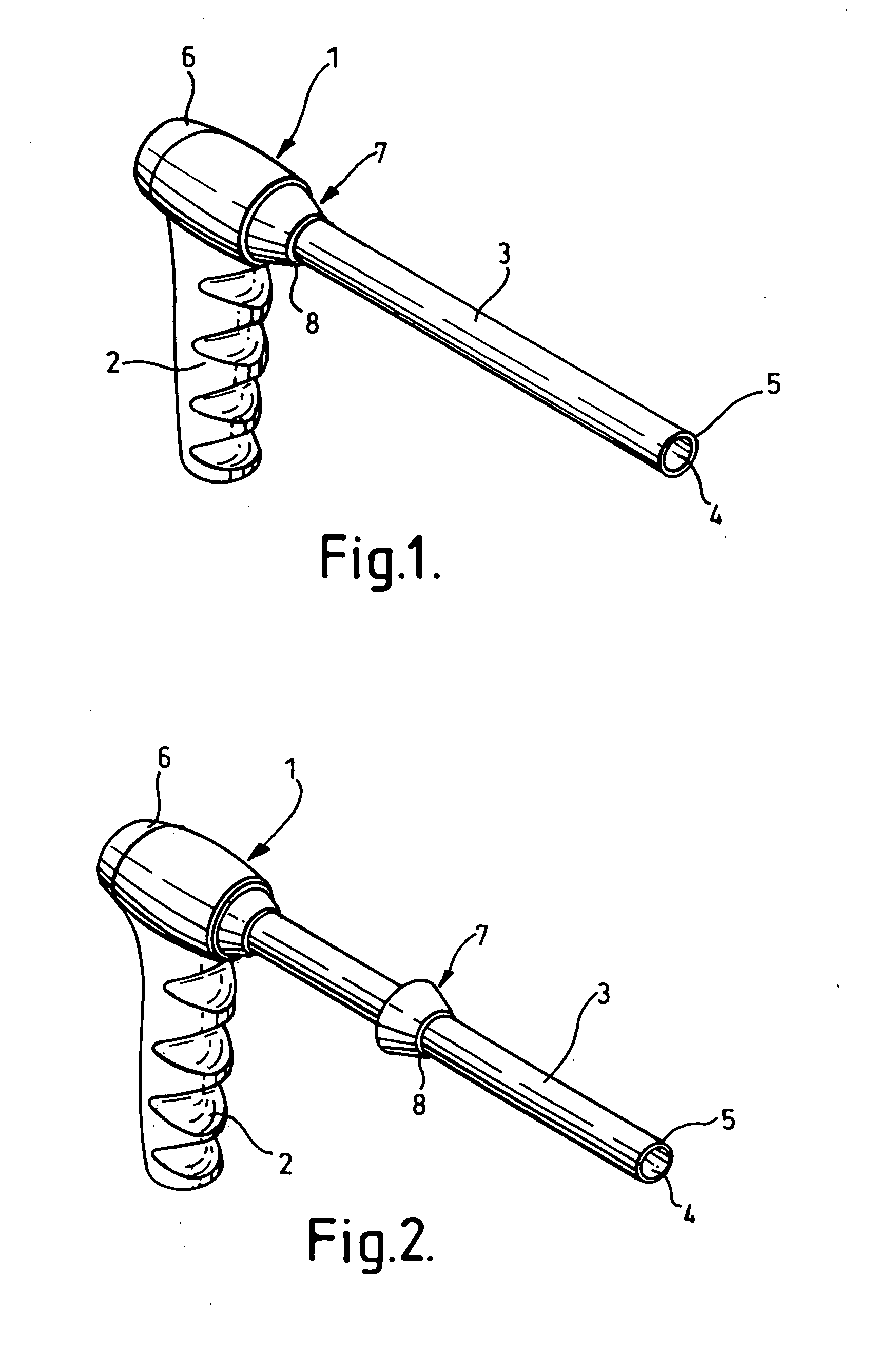
[0019]Referring to the drawings, FIG. 1 shows a morcellating device 1 comprising a handle 2 and a cylindrical tube 3. The cylindrical tube 3 is hollow, and defines a lumen 4 therein. The distal end of the tube 3 is provided with an electrosurgical electrode assembly 5. A tissue-pulling device (not shown) is insertable into the tube 3 from the proximal end 6 thereof, the distal end of the tissue-pulling device extending in use beyond the electrode assembly 5 at the distal end of the tube 3 for gripping tissue and pulling the tissue against the electrode assembly to form a core of severed tissue within the tube. The morcellating device 1 and the tissue-pulling device are described in greater detail in the specification of our International patent application WO 2005 / 112806.

[0020]The morcellating device is provided with a depth stop 7 which can be fixed to the outer circumference of the tube 3 at any position along its length. FIG. 1 shows the depth stop 7 in its non-operational (store...


PUM


Abstract

A tissue morcellating device (1) is provided for morcellating tissue within a body cavity of a patient. The morcellating device (1) comprisies a hollow tube (3) having a distal end portion, and tissue cutting means (5) located at the distal end of the tube, such that, when relative movement is initiated between the tube and the tissue, a core of severed tissue is formed within the tube for removal from the body cavity of the patient through the hollow tube. The hollow tube (3) is provided with a stop mechanism (7) which is longitudinally adjustable with respect to the hollow tube (3), the stop mechanism being provided with a shoulder (8) for limiting the longitudinal insertion of the tube into the patient's body.

Description

BACKGROUND OF THE INVENTION[0001]This invention relates to a tissue morcellating device for use in the bulk removal of tissue, as in a laparoscopic hysterectomy.[0002]In a laparoscopic hysterectomy, the body of the uterus is resected from the stump or fundus, and then removed from the operative site. To enable the uterus to be removed through a limited surgical opening, it is desirable to morcellate it into relatively smaller pieces of tissue, which are easier to remove. The present invention relates to an instrument and method for morcellating and removing a uterus.[0003]US patent specifications U.S. Pat. Nos. 5,957,884, 6,007,512 and 6,036,681 describe morcellating devices in which an element carrying an electrode is rotated in order to cause the morcellation of tissue. This rotation of the electrode necessitates a mechanical drive arrangement, which increases the complexity of the instrument. The specification of our International patent application WO 2005 / 112806 seeks to provid...

Claims


Application Information

Patent Timeline
Patent Type & Authority Applications(United States)
IPC IPC(8): A61B17/32
CPCA61B18/1442A61B18/1485A61B2019/306A61B2019/304A61B2017/320775A61B2090/034A61B2090/036A61B17/32A61B17/42
Inventor BATCHELOR, KESTER J.FLEMING, ALISTAIR I.JAMES, RHODRI G.EDWARDS, THOMAS R. K.
Owner GYRUS MEDICAL LTD
Learn More