Prosthesis systems and methods

a technology of prosthesis and system, applied in the field of prosthesis, can solve the problems of causing aneurysm formation, causing aneurysm formation, and causing aneurysm growth, and achieve the effect of reducing the risk of ruptur

Active Publication Date: 2008-03-13
MEDTRONIC VASCULAR INC
View PDF23 Cites 27 Cited by
  • Summary
  • Abstract
  • Description
  • Claims
  • Application Information

AI Technical Summary

Problems solved by technology

The weakening of a vessel wall from damage or disease can lead to vessel dilatation and the formation of an aneurysm.
Left untreated, an aneurysm can grow in size and may eventually rupture.
The rupture of an aortic aneurysm results in massive hemorrhaging and has a high rate of mortality.
The prosthetic grafts for these procedures are usually unsupported woven tubes and are typically made from polyester, ePTFE or other suitable materials.
However, these procedures require a large surgical incision and have a high rate of morbidity and mortality.
In addition, many patients are unsuitable for this type of major surgery due to other co-morbidities.
These graft attachment means do not provide the same level of attachment when compared to suture and can damage the native vessel upon deployment.

Method used


Image

  • Prosthesis systems and methods
  • Prosthesis systems and methods
  • Prosthesis systems and methods

Examples


Embodiment Construction

I. Tissue Reinforcement Prosthesis

[0023] A. Structure

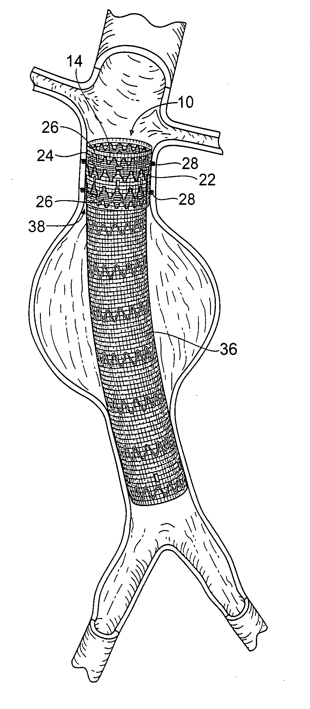
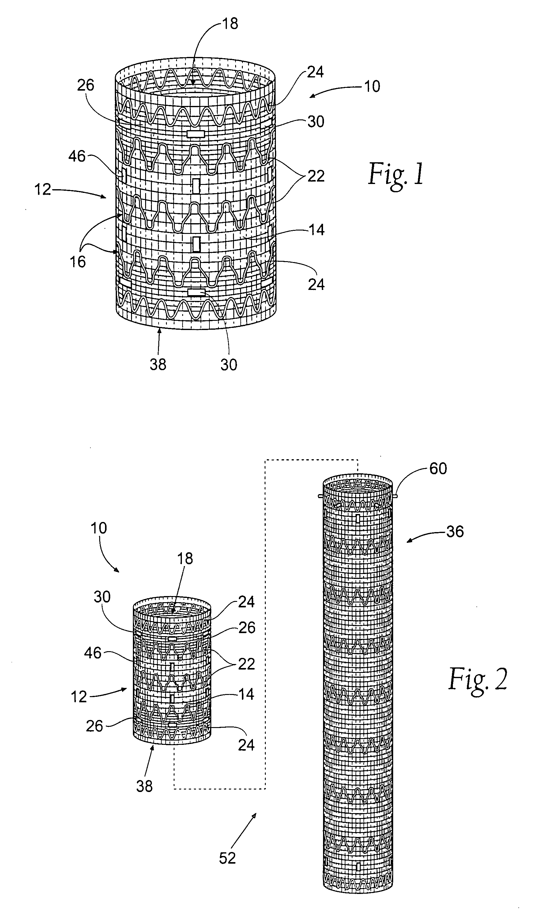
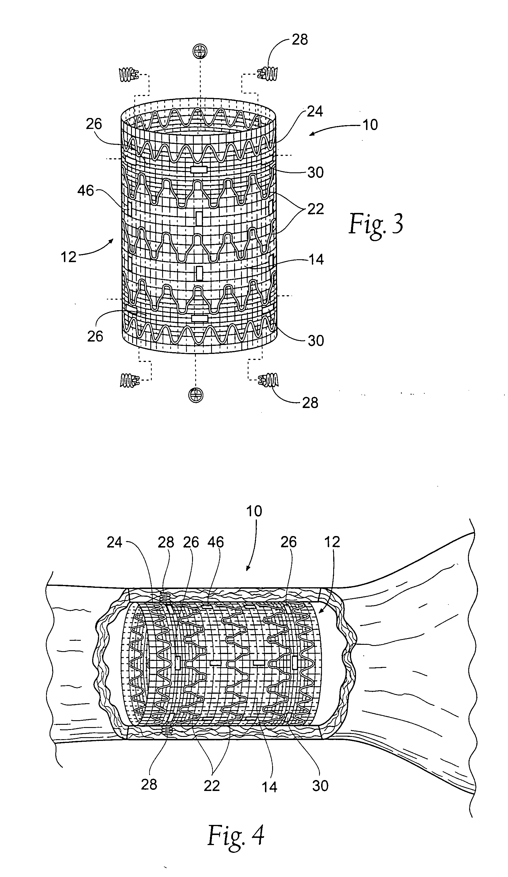
[0024]FIG. 1 shows a tissue reinforcement prosthesis 10 that embodies features of the invention. The prosthesis 10 serves to reinforce a region of a vessel wall or hollow body organ which has been weakened by disease or damage. As will be described in greater detail later, the prosthesis 10 desirable provides a platform on which to deploy a second prosthesis 36 (see FIG. 2) in the vessel or hollow body organ. In this arrangement, the reinforcement prosthesis 10 comprises a component part of an overall prosthesis system 52.

[0025] In the illustrated embodiment (see FIG. 1), the prosthesis 10 comprises a tubular trunk 12. The trunk 12 is sized and configured to fit within a targeted region of a hollow body organ and / or a blood vessel. The targeted region is selected on the basis of certain anatomic characteristics. These characteristics include a weakened conditioned caused, e.g., by disease or damage.

[0026] The trunk 12 forms a g...


PUM


Abstract

Systems and methods for deploying a prosthesis in a tissue region in a hollow body organ or blood vessel provide a first prosthesis and a second prosthesis, each having a prosthetic material and a scaffold that supports the prosthetic material. The first prosthesis has a proximal neck region, and the second prosthesis has an end region. The end region is sized and configured to telescopically fit with the proximal neck region to form a composite prosthesis. The systems and methods manipulate a fastener attachment assembly to implant at least one fastener to secure the composite prosthesis in the tissue region.

Description

RELATED APPLICATION [0001] This application is a divisional of U.S. patent application Ser. No. 10 / 752,435, filed Jan. 6, 2004, which is a continuation-in-part of U.S. patent application Ser. No. 10 / 693,255, filed Oct. 24, 2003, and entitled “Multi-Lumen Prosthesis Systems and Methods,” which claims the benefit of provisional U.S. patent application Ser. No. 60 / 489,011, filed Jul. 21, 2003, and entitled “Bifurcated Prosthesis Systems and Methods” and which is also a continuation-in-part of co-pending U.S. patent application Ser. No. 10 / 271,334, filed Oct. 15, 2002, entitled “Endovascular Aneurysm Repair System,” which claims the benefit of U.S. Provisional Patent Application Ser. No. 60 / 333,937, filed Nov. 28, 2001.FIELD OF THE INVENTION [0002] The invention relates generally to prostheses, and in particular, to prostheses used in the repair of diseased and / or damaged sections of a hollow body organ and / or a blood vessel. BACKGROUND OF THE INVENTION [0003] The weakening of a vessel ...

Claims


Application Information

Patent Timeline
Patent Type & Authority Applications(United States)
IPC IPC(8): A61F2/06A61B17/00A61B17/064A61B17/068A61F2/00A61F2/90
CPCA61B17/064A61F2/89A61B2017/003A61B2017/0646A61B2017/0649A61F2/064A61F2/07A61F2/90A61F2002/065A61F2002/067A61F2002/075A61F2250/0017A61F2250/0023A61F2250/0039A61B17/068
Inventor BOLDUC, LEEPARODI, JUAN
Owner MEDTRONIC VASCULAR INC
Why Eureka
Try Eureka