
Method and computer program for reducing power consumption of a computing system

a computing system and power consumption technology, applied in multi-programming arrangements, liquid/fluent solid measurement, instruments, etc., can solve the problems of reducing performance, unable to reduce the cost required for supplying power to unable to reduce the power consumption of the whole computing system, so as to reduce the power consumption

Inactive Publication Date: 2008-03-13
HITACHI LTD
View PDF18 Cites 37 Cited by
  • Summary
  • Abstract
  • Description
  • Claims
  • Application Information

AI Technical Summary

Benefits of technology

The present invention provides a method, system, and computer program for reducing power consumption in a computing system with multiple servers connected by a network and running one or more jobs. The method involves obtaining power properties of each server and the performance requirements for each job, searching for jobs to be relocated and destination servers to fulfill the performance requirements, relocating jobs to destination servers, and controlling power supply to turn off unused servers. The invention can help reduce power consumption and cost of supplying power to the whole computing system, while complying with service level agreements.

Problems solved by technology

However, the technique as described above allows for reducing the power consumption of a computing system in an area, but cannot reduce the power consumption of the whole computing system covering all the areas and, therefore, cannot reduce the cost required for supplying power to the whole computing system.
However, by the technique for power consumption reduction by decreasing the CPU operating frequency, the server performance is decreased, which results in a decrease in the performance of a job being run on the server.
This may result in that performance requirements for the job such as Service Level Agreement (SLA) required of the computing system by a user to run the job required by a user cannot be fulfilled.

Method used


Image

  • Method and computer program for reducing power consumption of a computing system
  • Method and computer program for reducing power consumption of a computing system
  • Method and computer program for reducing power consumption of a computing system

Examples


embodiment 1

[0047] In the following, illustrative embodiments of the present invention will be described with the drawings.

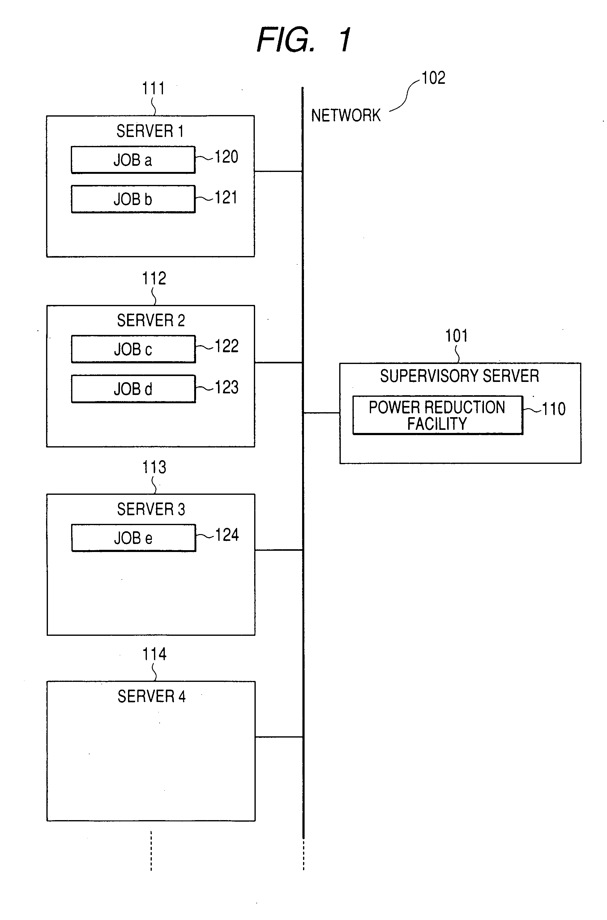
[0048]FIG. 1 shows an overall structural diagram of a computing system according to a first embodiment of the present invention. The computing system of the present embodiment comprises a plurality of servers 111-114 and a supervisory server 101. The servers 111-114 and the supervisory server are interconnected through a network 102. On the servers 111-114, jobs 120-124 are running. However, a server with no job running on it may exist like a server 114. In the figure, the jobs 120-124 are particularly appended with identifiers like Job a and Job b, if their contents are different.

[0049] Here, the jobs 120-124 are generic terms used to refer to programs which perform processing in response to an input and returns an output. A job may be, for example, an application program, EJB (registered trademark) application, Java (registered trademark) application, and one of process...

embodiment 2

[0075] A second embodiment (Embodiment 2) of the present invention is a method for intensive allocation of jobs to a subset of the servers, based on an event triggering the power reduction procedure by the power reduction facility 110 in Embodiment 1. A combination of the second embodiment and any other embodiment can be regarded as one embodiment of the present invention.

[0076]FIG. 20 shows details of the power reduction facility 110A in the second embodiment. Difference from Embodiment 1 lies in that the power reduction facility is provided with a trigger event detecting facility 420 which detects what event triggers the procedure of the invention illustrated in FIG. 7 in Embodiment 1. The trigger event detecting facility 420 detects one of the trigger events as will be specified below and starts the procedure illustrated in FIG. 7 in Embodiment 1. The trigger events are addition and removal of a server to / from the computing system; addition and removal or completion of a job, ch...

embodiment 3

[0077] A third embodiment (Embodiment 3) of the present invention is a method of obtaining server power properties from a power property measuring function installed in each server in the server properties obtaining function in Embodiment 1. A combination of the third embodiment and any other embodiment can be regarded as one embodiment of the present invention.

[0078]FIG. 21 shows an overall structural diagram of the computing system in Embodiment 3. Difference from Embodiment 1 lies in that each server 111A-114A is provided with a power property measuring function 2101. The power property measuring function 2101 can measure performance that the server utilizes (utilization performance) and the amount of power consumed by the whole server at the time as well as the amount of power consumed by each of its components and can report its measurement values to the power reduction facility 110.

[0079]FIG. 22 shows a detailed structure of each server 111A-114A in the third embodiment, whe...


PUM


Abstract

In a computing system where multiple servers are connected through a network and one or more jobs are run, a power reduction facility of a supervisory server relocates jobs according to predetermined conditions, thereby reducing the amount of power consumed by the computing system. For relocating the jobs, the power reduction facility obtains server-related information such as the power properties of the servers constituting the computing system and job-related information such as performance requirements for the jobs which are run in the computing system, and searches for one or more jobs to be relocated and destination servers, based on these server-related information and job-related information, to the extent that the performance requirements for each job are fulfilled. Based on the search results, the jobs are relocated to the destination servers, and servers on which no job is running, in consequence of the relocation, are powered off.

Description

CLAIM OF PRIORITY [0001] The present application is a continuation of application Ser. No. 11 / 522,374, filed Sep. 18, 2006, which claims priority from Japanese application serial JP 2006-141426 filed on May 22, 2006, the contents of which are hereby incorporated by reference into this application.BACKGROUND OF THE INVENTION [0002] The present invention relates to a technique for reducing the power consumption of a computing system. [0003] For information processing equipment such as servers which constitute a computing system, the amount of power consumed by each server increases with enhanced server performance. Further, the use of high-density information processing systems such as blade servers requires a huge amount of power to be distributed to them at a high density. Thus, the cost required for supplying power to such information processing equipment and / or systems and cooling them increases more and more. [0004] In view hereof, in a distributed processing system such as a gri...

Claims


Application Information

Patent Timeline
Patent Type & Authority Applications(United States)
IPC IPC(8): G06F1/32G06F9/46
CPCG06F1/3203G06F1/329G06F9/5088Y02B60/162Y02B60/142Y02B60/144G06F9/5094Y02D10/00
Inventor HATASAKI, KEISUKENAKAJIMA, TAKAOTAKAMOTO, YOSHIFUMI
Owner HITACHI LTD
Learn More