Method for changing force control gain and die cushion control apparatus

a technology of force control and gain control, applied in the field of methods, can solve the problems of excessive number of repeated trials, unstable control system, and inability to adjust the force control, so as to improve the responsiveness of the force control and improve the reliability of the force control. , the effect of precise pressing of a three-dimensional shap

Active Publication Date: 2008-03-20
FANUC LTD
View PDF9 Cites 15 Cited by
  • Summary
  • Abstract
  • Description
  • Claims
  • Application Information

AI Technical Summary

Benefits of technology

[0014] In this way, a force control gain can be changed easily and accurately in accordance with variation of characteristics of press machines and changes in the conditions of press operation, so that res

Problems solved by technology

If the determined value of the force control gain is not appropriate, a control system may become unstable due to oscillations or excessive overshoots.
If the force control gain is too great, the press machine or the accessories of the press machine may be broken or damaged.
However, there is a problem with a force control gain that may be affected by the operational environment (such as inertia,

Method used


Image

  • Method for changing force control gain and die cushion control apparatus
  • Method for changing force control gain and die cushion control apparatus
  • Method for changing force control gain and die cushion control apparatus

Examples


Embodiment Construction

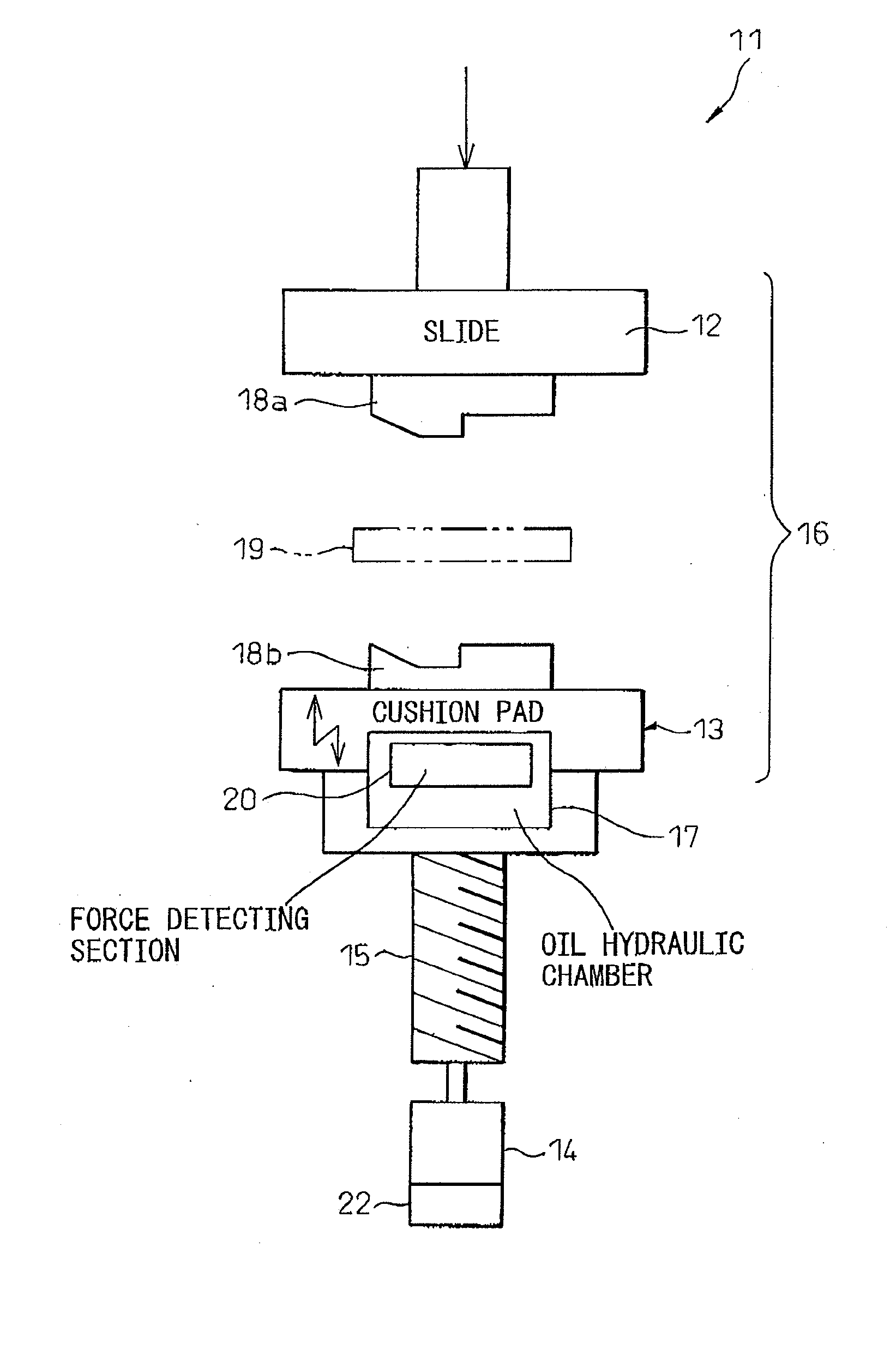
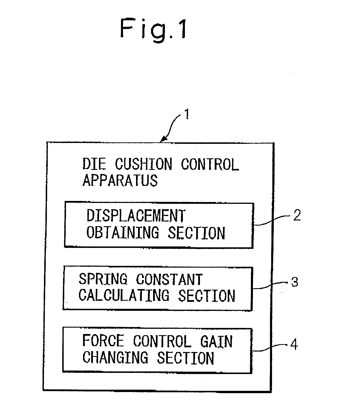
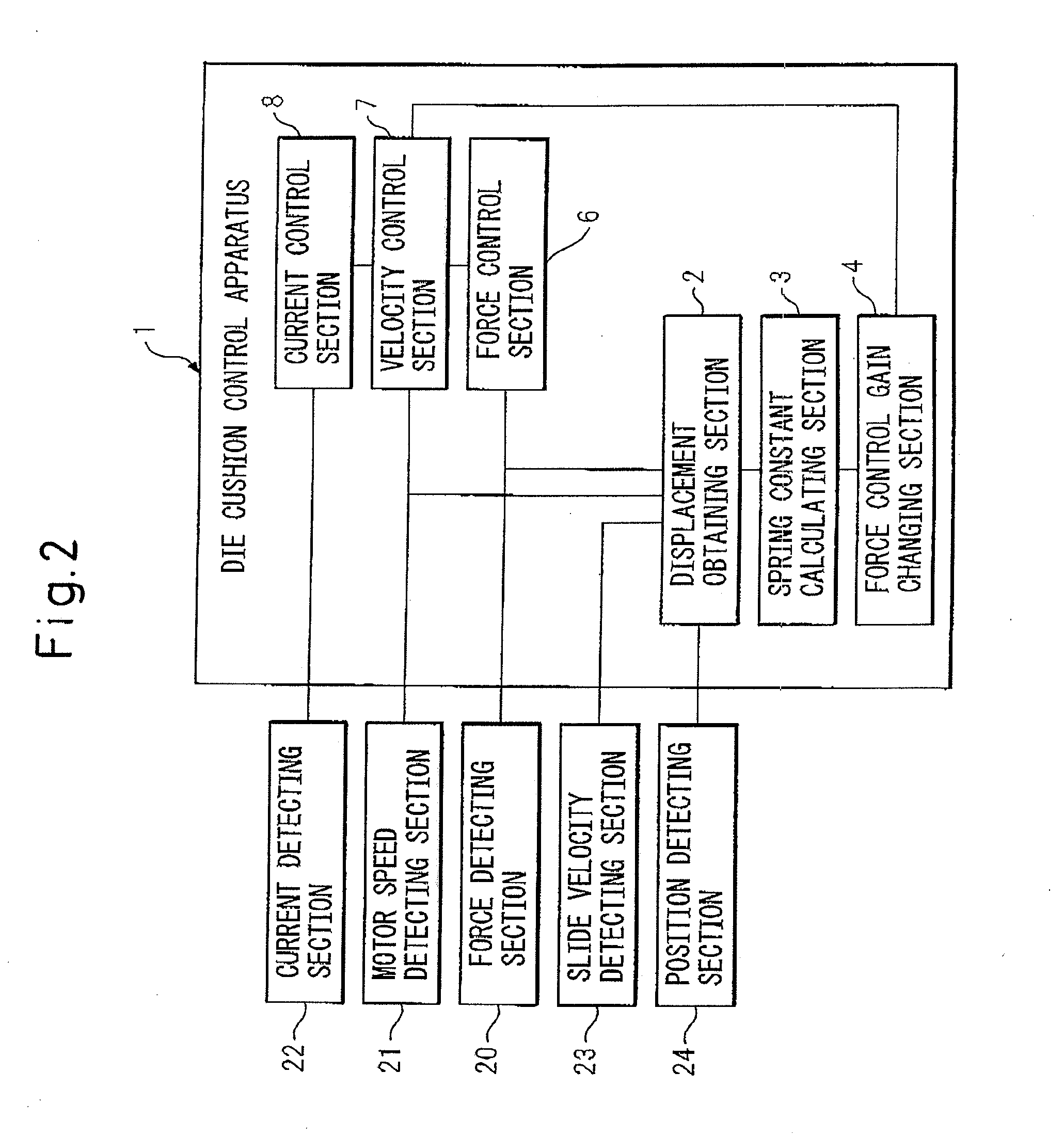
[0025] The embodiments of the present invention will now be described in detail below with reference to drawings showing specific examples thereof. In FIG. 1, a die cushion control apparatus according to an embodiment of the present invention is shown. The die cushion control apparatus of this embodiment is a die cushion control apparatus 1 which uses a servo motor 14 to perform force control of a die cushion 13 that is operated opposite to a slide 12 of a press machine 11 shown in FIG. 3 (shown only in part) and cooperates with slide 12 to exert a specified force to a pressed work piece 19. Slide 12 is situated on the upper side of press machine 11 and is adapted to be moved up and down by an oil hydraulic cylinder (not shown) as a driving source. Die cushion 13 is situated on the lower side of press machine 11 and is adapted to be moved up and down by a servo motor 14 via a ball screw 15. When slide 12 and die cushion 13 collide via pressed work piece 19, a force is exerted betwee...


PUM

PropertyMeasurementUnit
Speedaaaaaaaaaa
Timeaaaaaaaaaa
Velocityaaaaaaaaaa

Abstract

A method for changing a force control gain expressed as a ratio of force error to velocity command value in a control circuit performing a force control of a servo motor driving a die cushion disposed opposite to a slide in a press machine. The method includes: obtaining a difference between a displacement of the slide and a displacement of the die cushion in a state in which the slide and the die cushion collide with and are exerting force on each other; detecting the force when the difference of the displacements is obtained; calculating a spring constant of a structural portion based on a proportionality between the difference of the displacements and the force, when regarding the structural portion including the slide and the die cushion as an elastic structure; and changing the force control gain based on the spring constant using a fixed proportionality that exists between the force control gain and a reciprocal of the spring constant.

Description

CROSS REFERENCE TO RELATED APPLICATION [0001] The present application claims the benefit of priority based on Japanese Patent Application No. 2006-254692, filed on Sep. 20, 2006, the disclosure of which is incorporated herein in its entirety by reference. BACKGROUND OF THE INVENTION [0002] 1. Field of the invention [0003] The present invention relates to a method for changing a force control gain and a die cushion control apparatus for changing the force control gain expressed as a ratio of force error to a velocity command value in a control circuit which uses a servo motor to perform force control of a die cushion such that a force of a specified value may be produced by a slide in a press in the interaction with the die cushion disposed opposite to the slide. [0004] 2. Description of the Related Art [0005] Generally, in a method for controlling a die cushion in force control using a servo motor such that a force of a specified value may be produced between a slide and a die cushi...

Claims


Application Information

Patent Timeline
IPC IPC(8): B21D22/00
CPCB21D24/02G05B2219/45143G05B2219/41251G05B19/237
Inventor IWASHITA, YASUSUKEOKITA, TADASHIKAWAMURA, HIROYUKIIKAI, SATOSHI
Owner FANUC LTD
Why Eureka
Try Eureka