
Actuator

a technology of actuators and actuators, applied in the field of actuators, can solve the problems of increasing the weight of the entire device, the distal end portion of the artificial arm (hand) becomes too heavy, and it is difficult to realize a small and light-weight motorized artificial arm or robot hand. the effect of increasing the length of the twisted string

Inactive Publication Date: 2008-03-20
NIDEC CORP
View PDF7 Cites 37 Cited by
  • Summary
  • Abstract
  • Description
  • Claims
  • Application Information

AI Technical Summary

Benefits of technology

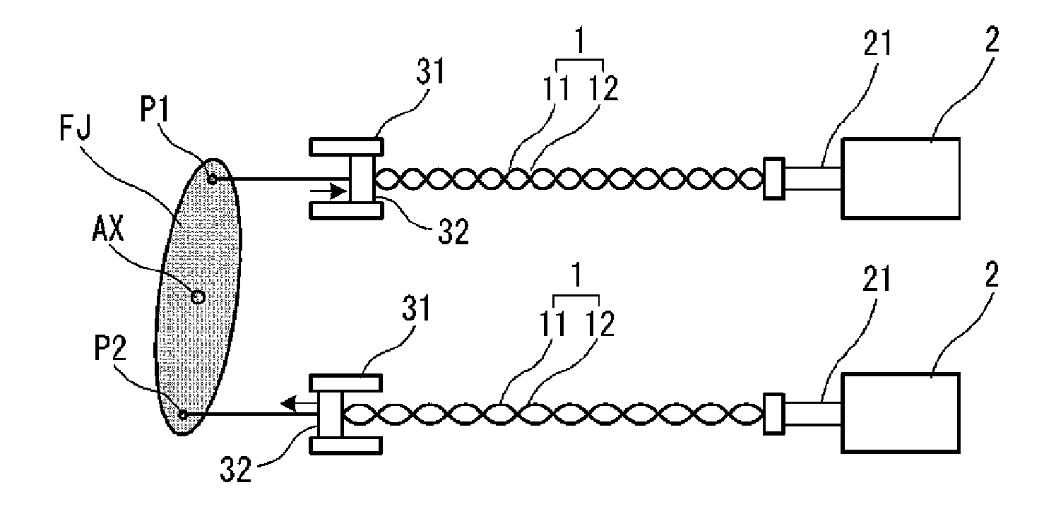
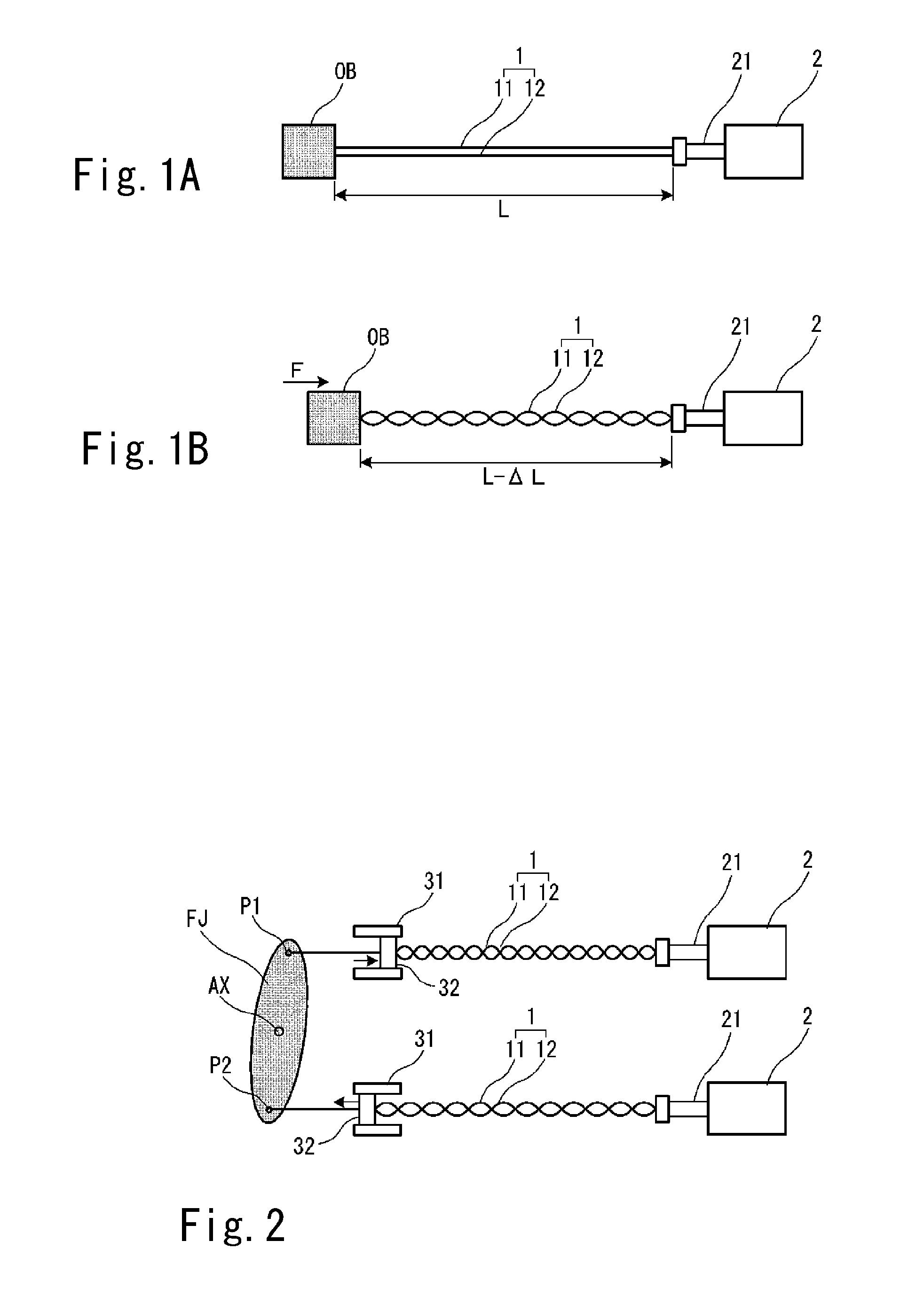
[0010] A preferred embodiment of the present invention provides an actuator using a motor and a twisted string having a structure in which two strings are twisted with each other. A first end of the twisted string is connected to a drive target while a second end of the twisted string is connected to a rotation shaft of the motor directly or indirectly via a power transmission mechanism. When a rotation shaft of the motor rotates, a twisted state of the two strings is tightened or loosened in accordance with a rotation direction of the rotation shaft, so that a length of the twisted string is decreased or increased when the motor rotates. As a result, the drive target is driven.
[0011] According to this structure, the twisted string converts the rotational movement in the twisting direction thereof (i.e., torque) into linear movement in the length direction (i.e., tension), so it works as a power transmission mechanism including a reduction gear. Therefore, a reduction gear having a multistage gear or the like becomes unnecessary, which can contribute largely to significant reductions in the size and the weight of the entire device. In addition, noise is not generated unlike the reduction gear having a multistage gear or the like, so that a silent actuator can be realized. Furthermore, since the twisted string is generally inexpensive compared with a reduction gear having a multistage gear or the like, the cost of the actuator can be reduced.
[0012] In addition, since there is flexibility and resilience to some extent between the rotational movement in the twisting direction and the linear movement in the length direction of the twisted string, a so-called soft actuator can be realized without using an elastic member such as a spring or an air cylinder. Thus, a compliance function like that of a human hand has can be realized easily.
[0014] According to this structure, a driving direction and a driving range of the drive target can be restricted easily by the slide guide and the slide member. In addition, flexibility in design about a distance between the motor and the drive target as well as a direction between them can be secured, so it is easy to satisfy a restriction of space where the actuator is mounted and to utilize the space effectively.
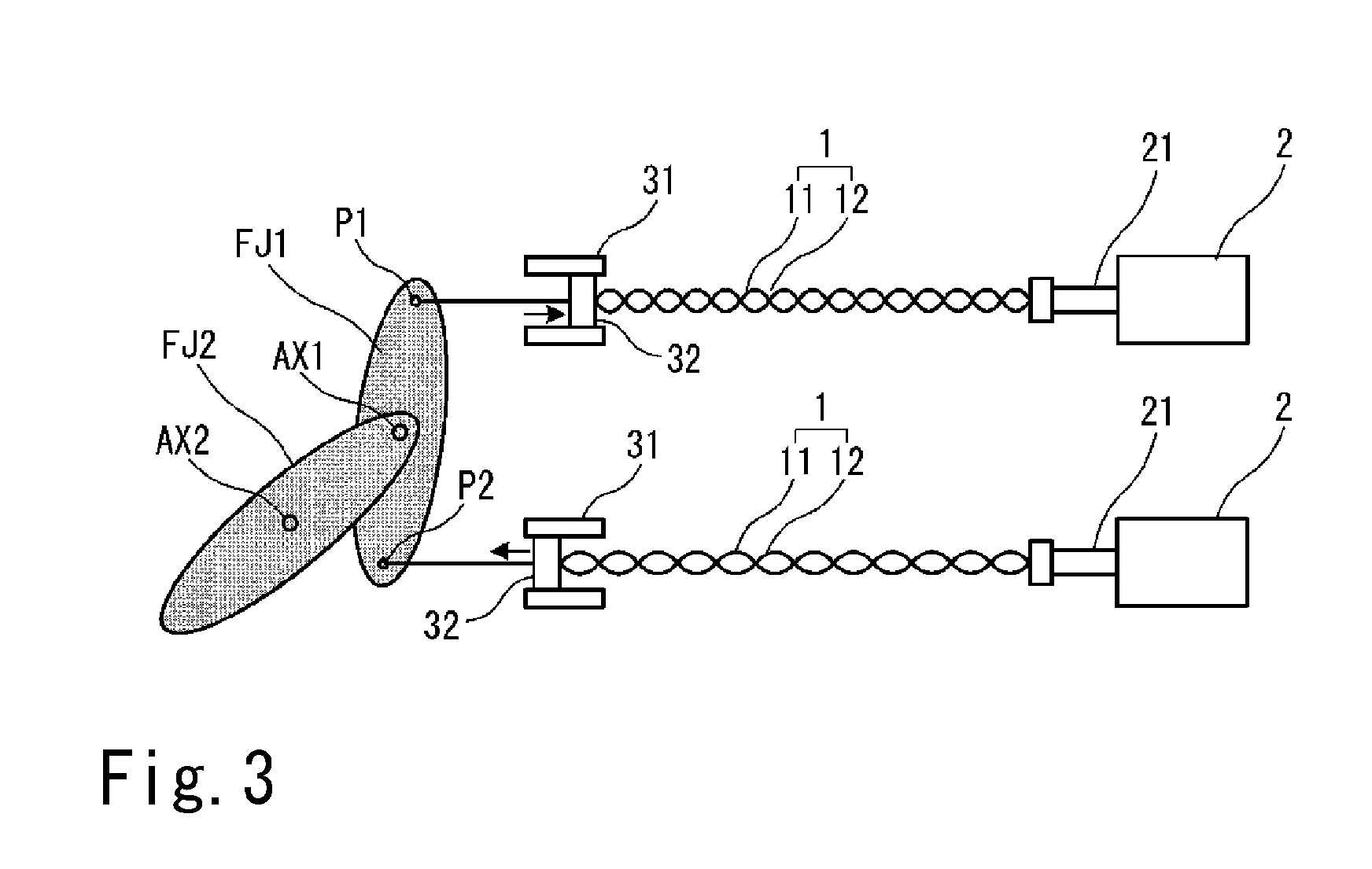
[0016] According to this structure, the twisted strings of the two actuator kits are driven in opposite directions. More specifically, one of the twisted strings is driven in a shortening direction while the other twisted string is driven in the extending direction, so that the finger joint can be driven easily and accurately.

Problems solved by technology

Although it is possible to obtain a large torque by a small motor with a reduction gear, the weight of the entire device will increase due to the weight of the reduction gear.
As a result, there will be a problem that a distal end portion of the artificial arm (hand) becomes too heavy, for example.
Therefore, it is difficult to realize a small and light-weight motorized artificial arm or robot hand.
Furthermore, there is another problem that noise is generated due to engagement of teeth of gears if the reduction gear defined by a multistage gear is used, adding to the problems involving weight and space described above.

Method used


Image

  • Actuator
  • Actuator
  • Actuator

Examples


Embodiment Construction

[0029] Hereinafter, preferred embodiments of the present invention will be described with reference to FIGS. 1A through 10. Note that relative positions and directions of members, which are described as upper, lower, left or right in the following description, are merely relative positions and directions in the drawings and do not mean actual relative positions and directions when they are installed in real equipment.

[0030]FIGS. 1A and 1B are schematic diagrams showing a concept of a twisted string actuator according to a preferred embodiment of the present invention. As shown in FIGS. 1A and 1B, the twisted string actuator according to the present invention preferably includes a motor 2 and a twisted string 1 that has a structure in which two strings or wires (hereinafter referred to as strings, simply) 11 and 12 are twisted loosely. FIG. 1A schematically shows the two strings 11 and 12 that are loosened to be two parallel strings, and FIG. 1B schematically shows the two strings 1...


PUM


Abstract

A twisted string actuator as a light-weight and space saving actuator includes a small motor and a twisted string having a structure in which two strings are twisted with each other loosely. A first end of the twisted string is connected to a finger joint, and a second end of the same is connected to a rotation shaft of the motor via a power transmission mechanism. When the rotation shaft of the motor rotates, a twisted state of the two strings of the twisted string is tightened or loosened, so that a length of the twisted string is decreased or increased. As a result, the finger joint is driven to rotate about the axis.

Description

BACKGROUND OF THE INVENTION [0001] 1. Field of the Invention [0002] The present invention relates to an actuator that can be used in a motorized artificial arm, a robot hand or the like. More specifically, the present invention relates to an actuator that utilizes a motor and a twisted string having a structure in which two strings are twisted with each other. [0003] 2. Description of the Related Art [0004] Conventionally, there is an actuator utilizing wires (or strings) and a motor (hereinafter referred to as a wire actuator) as described in Japanese unexamined patent publications Nos. 6-8178 and 7-96485. Among various wire actuators utilizing a motor and wires or strings (hereinafter referred to as strings, simply) for finger joints, a structure having a concept that is related to the present invention is shown in FIG. 11 as a basic concept. [0005] In FIG. 11, a rotating member 102 such as a pulley is connected to a rotation shaft 101a of a motor 101 via a reduction gear. Alterna...

Claims


Application Information

Patent Timeline
Patent Type & Authority Applications(United States)
IPC IPC(8): B23Q16/02
CPCA61F2/54A61F2/60A61F2/68Y10T74/1476A61F2002/701B25J9/104B25J9/1075A61F2002/6836A61F2/70
Inventor MURATA, ITSUOYOKOI, HIROSHIYAMASHITA, MAKOTO
Owner NIDEC CORP
Learn More