Radially expandable downhole fluid jet cutting tool

a cutting tool and radial expansion technology, applied in the direction of fluid removal, drilling machine and method, borehole/well accessories, etc., can solve the problems of limited use of the tool in u.s. patent no. 5,765,756, time-consuming and costly removal of the tool for resetting and subsequent repositioning in the well, and achieves convenient and quick relocation and easy and efficient cutting of the casing

Active Publication Date: 2008-03-20
BAKER HUGHES INC
View PDF9 Cites 21 Cited by
  • Summary
  • Abstract
  • Description
  • Claims
  • Application Information

AI Technical Summary

Benefits of technology

[0007]The present invention overcomes the deficiencies of U.S. Pat. No. 5,765,756 while providing additional benefits not found in prior jet cutting tools. For example, the jet cutting tools and methods of cutting a surface of a wellbore of the present invention provide the capability to extend and retract the jetting nozzles for easy and quick relocation and redeployment within a well without the need for removal of the tool from the well; permit the jetting nozzles to be consistently extended to the cutting surface; maintain the jetting nozzles in the appropriate orientation during cutting; permit easy and efficient cutting of casing when passing through a restriction in the casing or when cutting a surface in relatively shallow water depth; permit efficient cutting in multiple locations within conduits having variable inner diameters; and provide the capability of cutting in large diameter conduits and then be redeployed for cutting in small diameter conduits without having to remove the tool from the wellbore.
[0009]After cutting, the pressure of the cutting fluid flowing through the passageway is decreased and the piston is retracted. Accordingly, the arms are also retracted so that the jet cutting tool can be moved to a new location and the arms redeployed for additional cutting. Advantageously, the retraction and the extension of the arms are fully repeatable such that the jet cutting tool can be used in multiple locations having multiple inner diameter, including cutting narrower portions of casing after cutting wider portions of casing.
[0015]The jet cutting tools and methods of cutting a surface in a wellbore disclosed herein have one or more of the following advantages: providing the capability of extending and retracting the jetting nozzles for easy and quick relocation and redeployment within a well; permitting the jetting nozzles to be consistently extended to the cutting surface; maintaining the jetting nozzles in the appropriate orientation during cutting; permitting easy and efficient cutting of casing when passing through a restriction in the casing or when cutting a surface in relatively shallow water depth; permitting efficient cutting in multiple locations within conduits having variable inner diameters; and providing the capability of cutting in large diameter conduits and then be redeployed for cutting in small diameter conduits without having to remove the tool from the wellbore.

Problems solved by technology

In those instances where the tool is to be moved to a new location for continued jetting, the telescopically extended jetting nozzles can not be reconfigured to a lesser extension because the telescoping members cannot be retracted to their original positions.
As a result, the tool in U.S. Pat. No. 5,765,756 is limited in its use and requires removal of the tool from the well and resetting of the telescoping jetting nozzles before the tool can be used in a new, narrower, location.
As is apparent, removal of the tool for resetting and subsequent repositioning in the well is time consuming and costly.

Method used


Image

  • Radially expandable downhole fluid jet cutting tool
  • Radially expandable downhole fluid jet cutting tool
  • Radially expandable downhole fluid jet cutting tool

Examples


Embodiment Construction

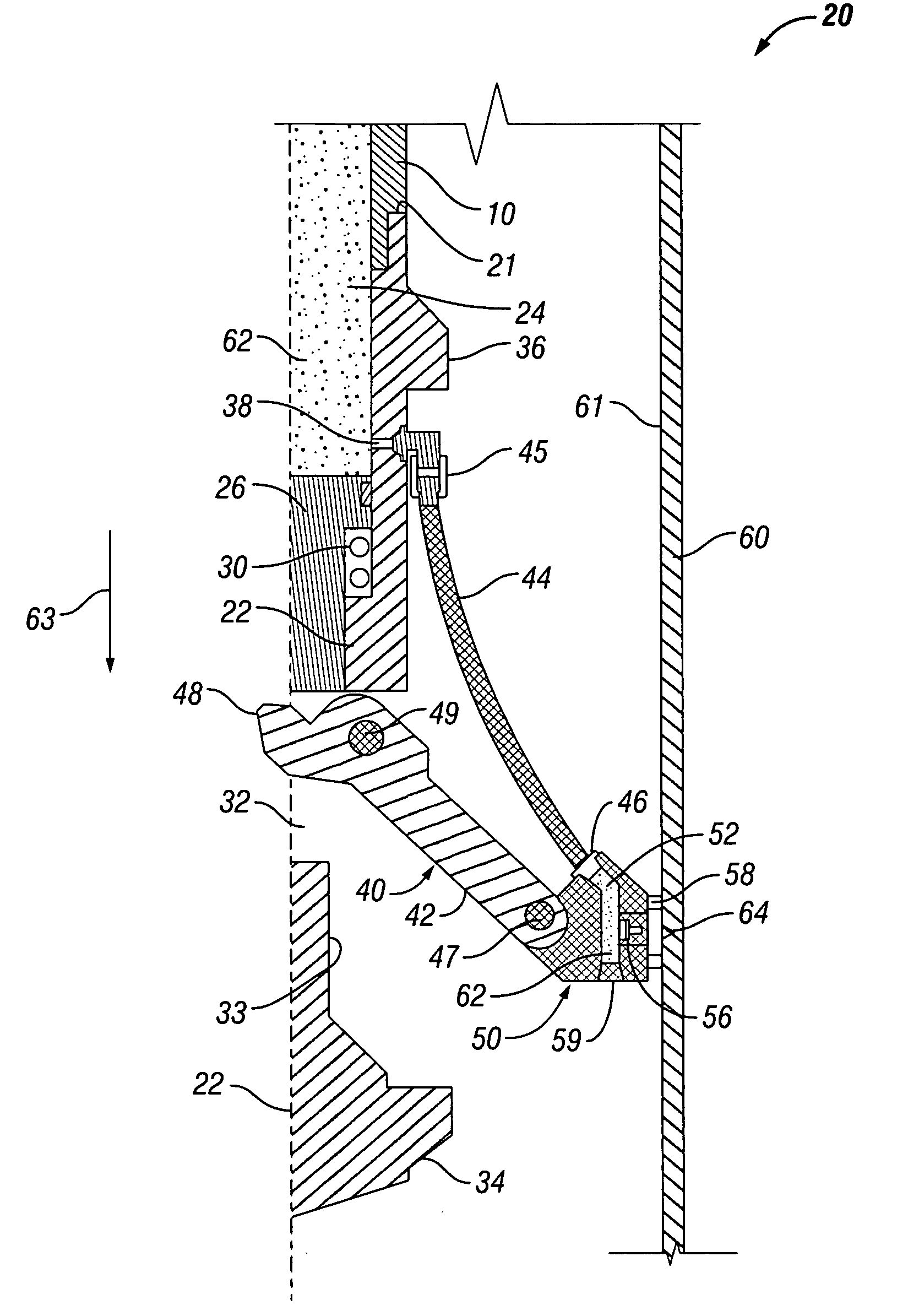
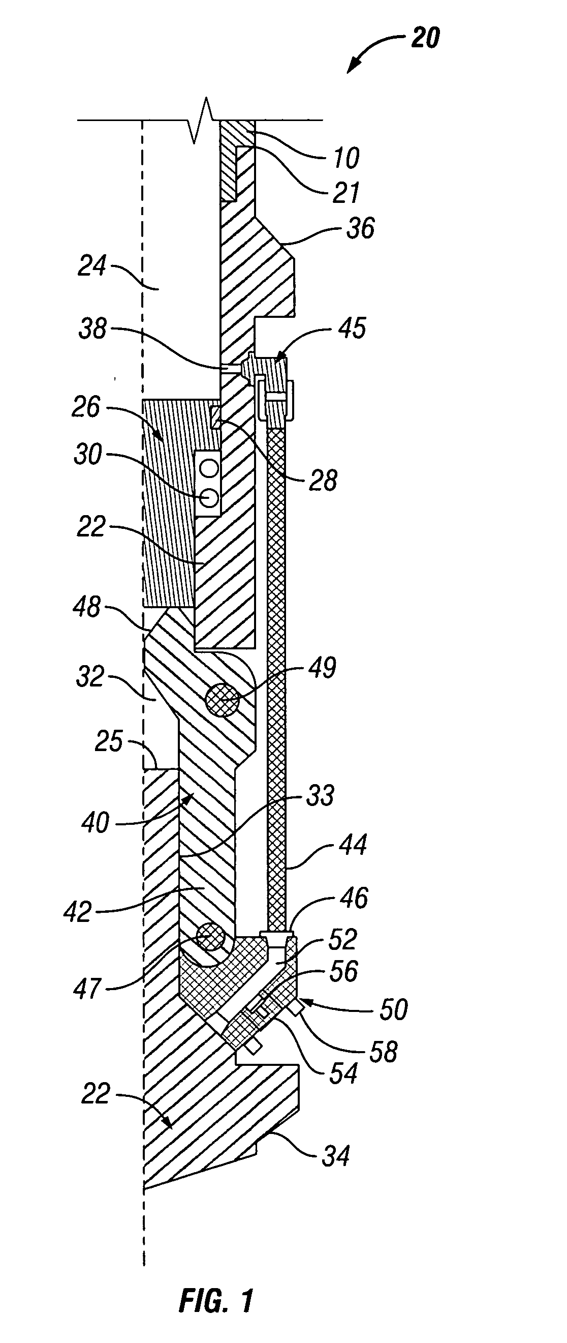
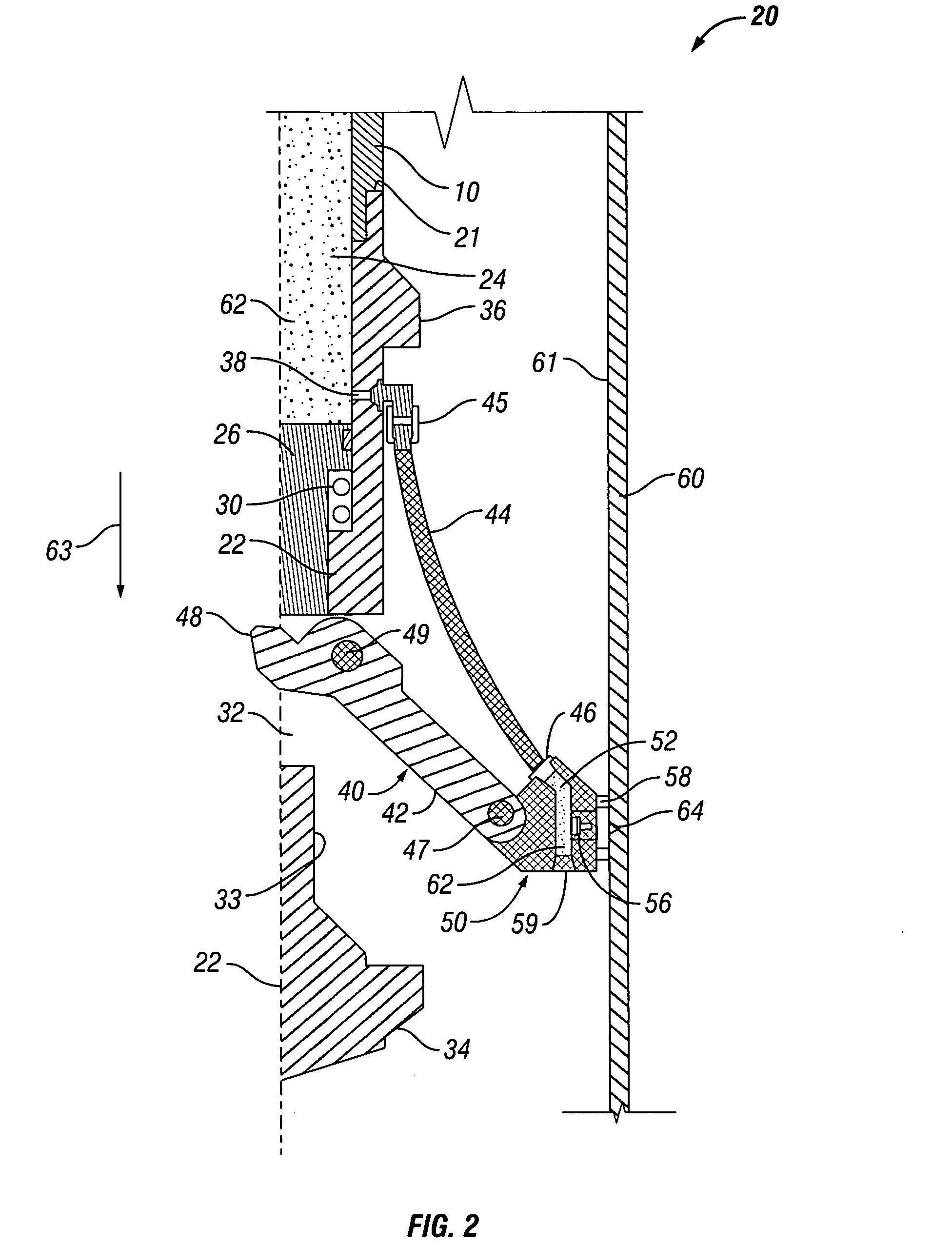
[0022]Referring now to FIGS. 1-2, jet cutting tool 20 is shown in its retracted or “run-in” position (FIG. 1) and an extended or cutting position (FIG. 2). Jet cutting tool 20 has housing 22 with passageway 24 extending longitudinally into upper end 23 of housing 22. Upper end 23 is adapted to be connected to string of conduit 10, such as tubing or drill pipe, through any device or method known to persons of ordinary skill in the art. The lower portion of housing 22 is solid, with passageway 24 having a bottom 25 approximately midway along the length of housing 22.

[0023]Actuating member such as piston 26 is slidingly engaged within passageway 24 of housing 22. Resilient seal 28 provides a seal with piston 26 along the wall of passageway 24. Preferably, a retaining member such as coil spring 30 is disposed adjacent piston 26 for urging piston 26 upward. As discussed in greater detail below, spring 30 is expanded when jet cutting tool 20 is in its retracted position (FIG. 1) and compr...


PUM


Abstract

Downhole fluid jet cutting tools having extendible and retractable arms with cutting heads on the ends are disclosed. The jet cutting tools permit casing and other downhole surfaces to be cut utilizing a cutting fluid forced through a jet nozzle assembly. Movement of a piston slidingly engaged within the passageway of the tool actuates the arms when cutting fluid pressure acts on the piston. As a result, the arms are extended and cutting fluid is forced at high pressure from the passageway to the cutting head where it is expelled through nozzles for cutting casing and the like. The jet cutting tools permit the arms to be extended, retracted, and re-extended or redeployed multiple times without the need for being retrieved from the wellbore.

Description

BACKGROUND[0001]1. Field of Invention[0002]The present invention is directed to a downhole cutting tool and, in particular, a downhole radially expandable fluid jet cutting tool.[0003]2. Description of Art[0004]Various types of cleaning or cutting jet blasting arrangements have been proposed and used for jet blasting or eroding surfaces with abrasive fluids including, by way of example only, steam, water or any other fluid along with or without an abrasive substance in an attempt to accomplish whatever results may be desired.[0005]Generally the fluids are conducted through a fluid passage in the arrangement and discharged through a restricted orifice in a jetting nozzle to increase the velocity of fluids and abrasive particles in an attempt to increase the cutting or cleaning effect desired. The jetting nozzle is available in a variety of designs and sizes and is normally produced from an extremely hard and / or tough material such as, by way of example only, carbide. It is generally ...

Claims


Application Information

Patent Timeline
Patent Type & Authority Applications(United States)
IPC IPC(8): E21B43/11
CPCE21B43/114E21B29/005
Inventor LYNDE, GERALD D.LAIRD, MARY L.
Owner BAKER HUGHES INC
Why Eureka
Try Eureka