Bit For Drilling A Hole

a drilling bit and drill bit technology, applied in the field of drilling, can solve the problems of limited openings between crown segments, brittle crown material, and risk of breaking a segment while drilling, and achieve the effect of convenient manufacturing

Active Publication Date: 2008-03-20
GROUPE FORDIA
View PDF2 Cites 24 Cited by
  • Summary
  • Abstract
  • Description
  • Claims
  • Application Information

AI Technical Summary

Benefits of technology

[0021] Advantageously, the reinforcing members increase the robustness of the segments. Accordingly, such segments can extend longitudinally away from the support over a greater distance than in drill bits wherein reinforcing members are not provided. These segments are relatively less prone to failure than non-reinforced segments and allow to manufacture drill bits having a relatively longer useful life because of the presence of the reinforcing members.
[0023] The bit is relatively easy to manufacture and is typically compatible with existing drilling equipments and methods. In some embodiments of the invention, the manufacturing method used to manufacture the crown causes deviations in the shape of the crown from a perfectly annular shape to be relatively small.

Problems solved by technology

However, this crown material is typically relatively brittle.
Accordingly, the dimensions of the openings between the segments in the crown are limited by the brittleness of the material used to manufacture these crowns.
Indeed, if these openings extend too deep within the crown, there is a risk that a segment will be broken while drilling.
Since these drill bits are relatively expensive, the size of the segments are typically limited in currently existing bits, as shallower openings between the segments render the latter typically less prone to being ruptured or otherwise damaged.
In addition, the time required to remove the drill bit and to position the new bit inside the bore that was being bored is typically relatively long as the bit and drilling apparatus need to be removed entirely from this bore in order to replace the damaged bit.
However, bits including relatively shallow openings will be worn from drilling in a relatively short amount of time.
Therefore, once more, there is a need to take time to remove the bit from the bore to drill at relatively short time intervals to replace the worn out drill bit.
However, the configuration of this drill bit is not suitable for use in wet drilling wherein water is injected inside the drill bit during the drilling process.
Indeed, the configuration of the cuts in this drill bit does not allow the water to flow radially outwardly towards the outside of the drill bit as no longitudinal passageways are present that would allow the water to move away from the crown of the drill bit after it exits the crown.
Another problem that sometimes occurs in prior art drill bit is that the drilling process may produce a radially uneven abrasion of the crown.

Method used


Image

  • Bit For Drilling A Hole
  • Bit For Drilling A Hole
  • Bit For Drilling A Hole

Examples


Embodiment Construction

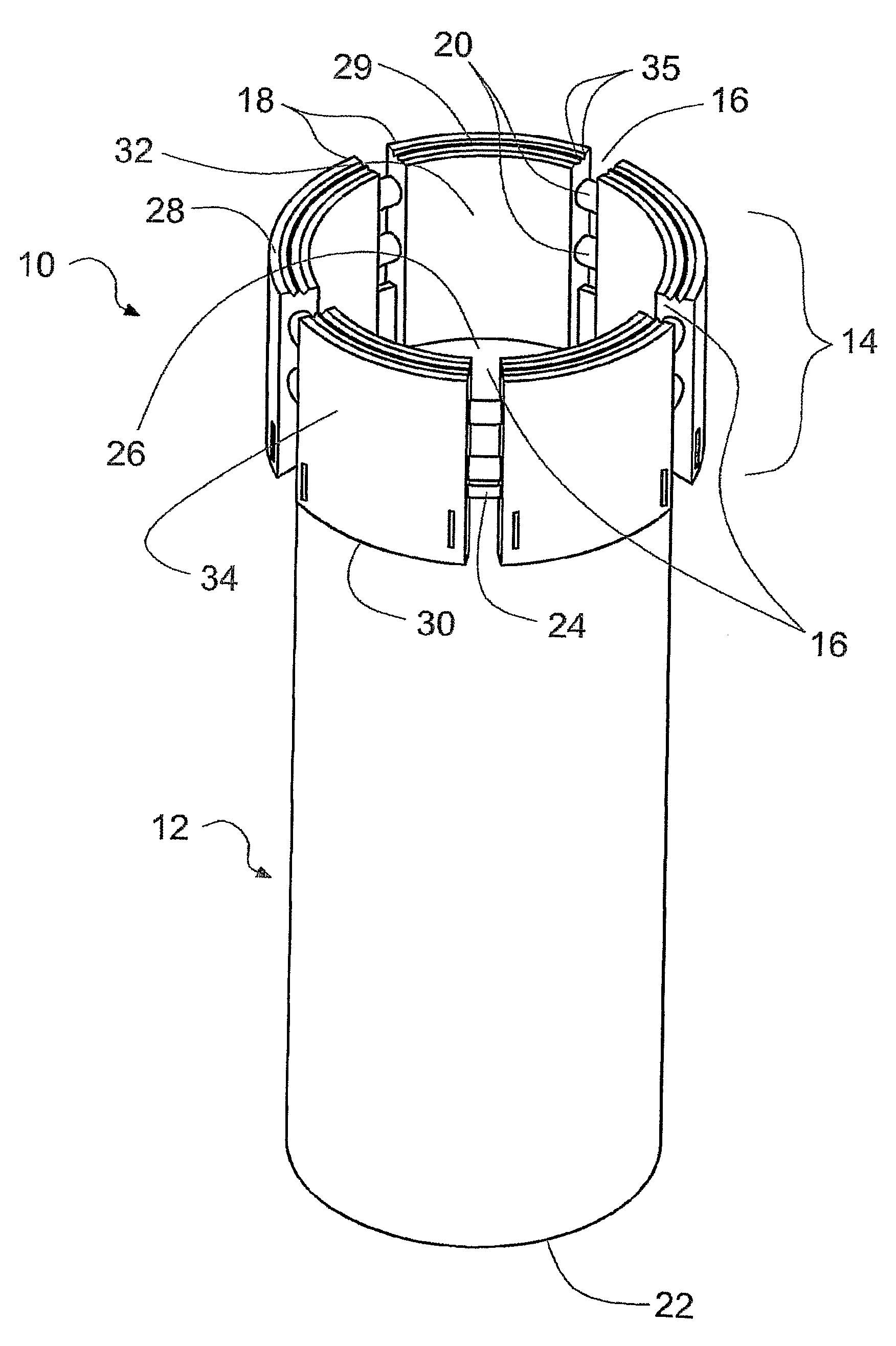
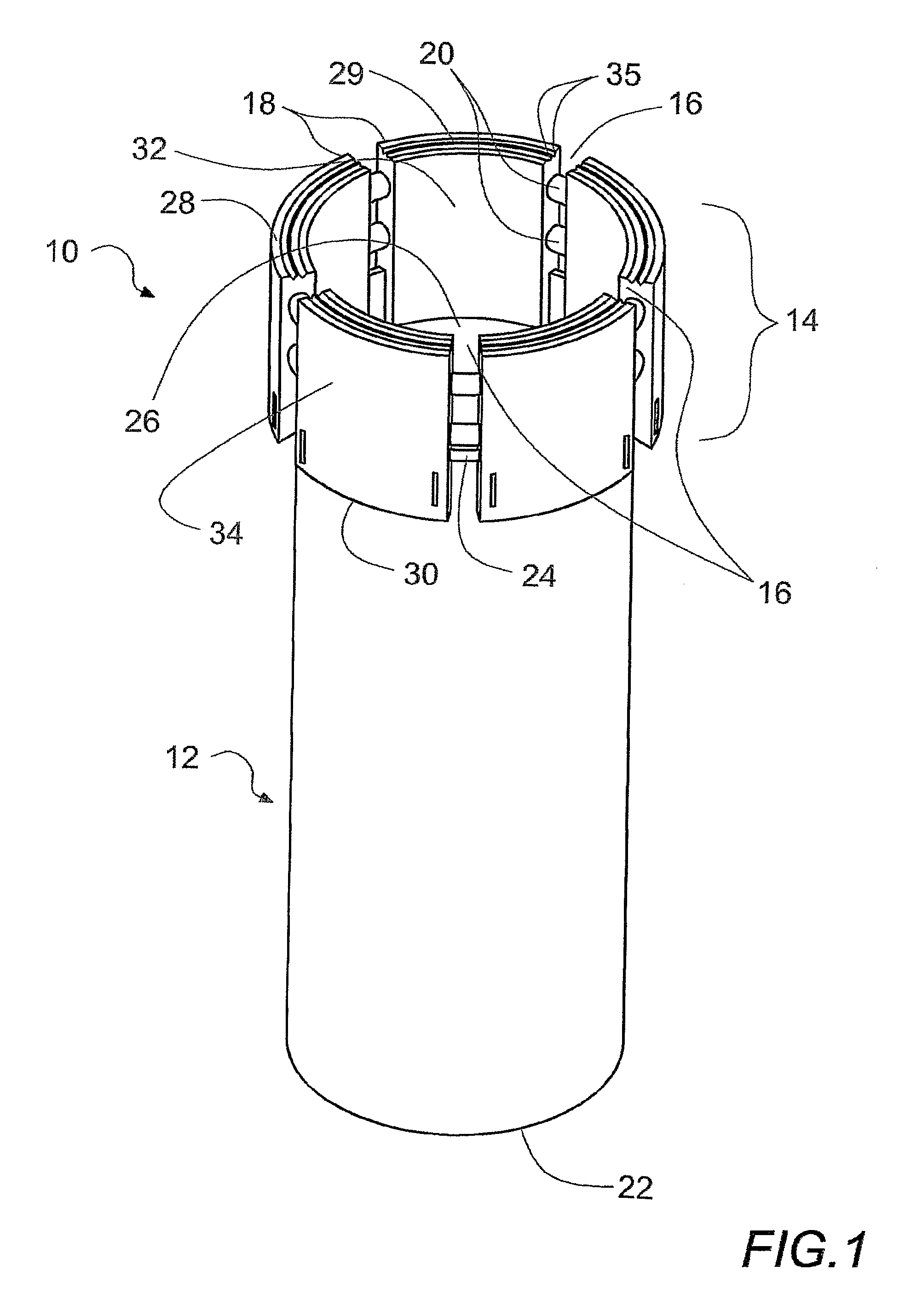
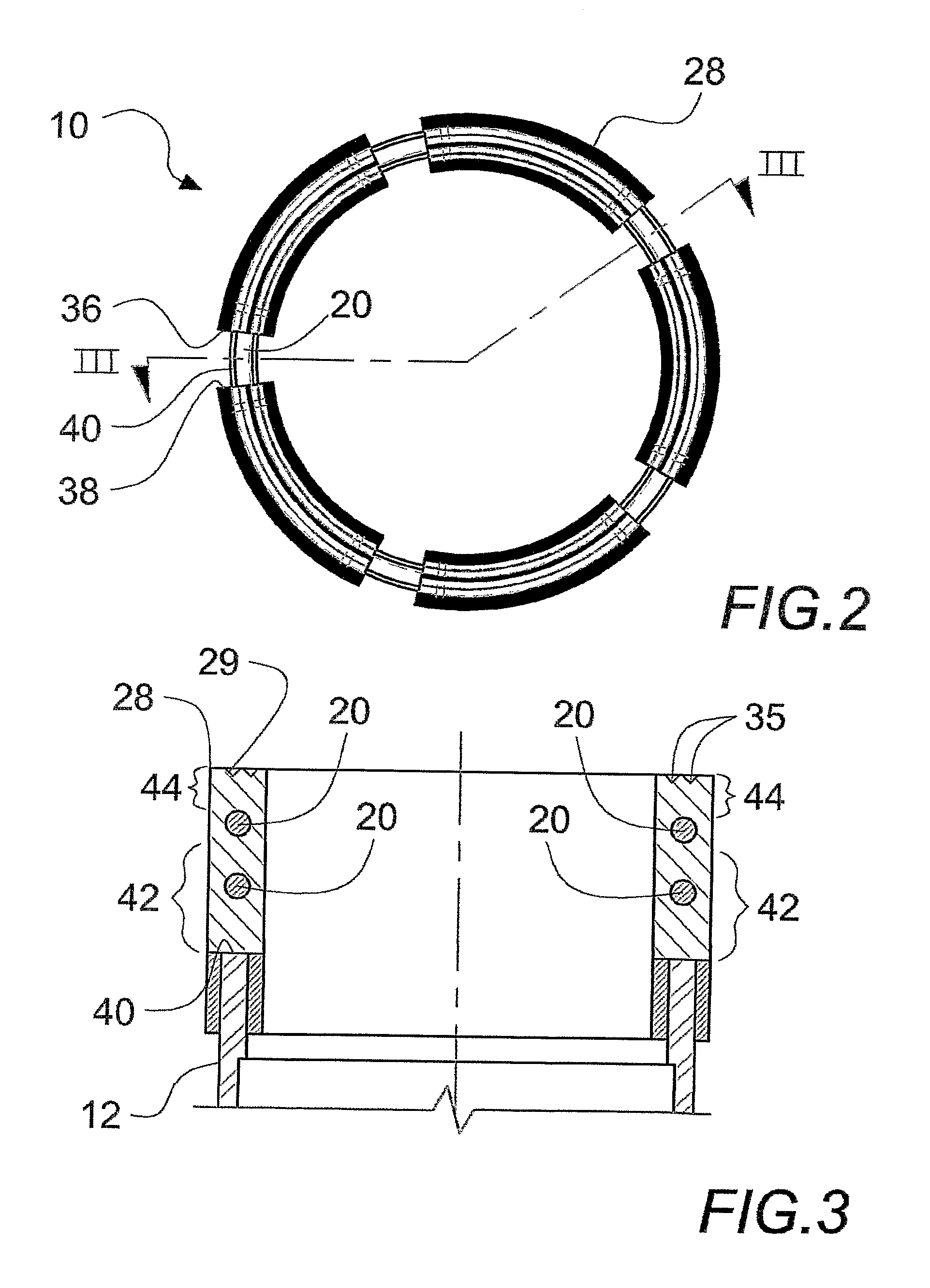
[0049]FIG. 1 illustrates a bit 10 for drilling a hole (not shown in the drawings). The bit 10 includes a support member 12 and a crown 14 extending from the support member 12. A plurality of slots 16 is formed into the crown 14 and defines a plurality of drilling segments 18. The bit 10 further includes a plurality of reinforcing members 20, each reinforcing member 20 extending between adjacent segments 18.

[0050] The reinforcing members 20 improve the structural integrity of the crown 14. Therefore, the crown 14 may extend longitudinally from the support member 12 over a distance that is larger than distances that would be achievable using prior art crown configurations.

[0051] Although the crown 14 shown in the drawings includes 5 slots, it is within the scope of the invention to have crowns that include fewer or more slots. Furthermore, in some embodiments of the invention, only one slot is formed into a crown of a bit.

[0052] The support member 12 defines a support member proxim...


PUM

PropertyMeasurementUnit
depthaaaaaaaaaa
inner diameteraaaaaaaaaa
outer diameteraaaaaaaaaa

Abstract

A bit for drilling a hole. The bit includes a support member, the support member having a passageway extending substantially longitudinally therethrough; a substantially annular crown defining a crown distal end and a crown proximal end, a radially inwardly located crown inner surface and a radially outwardly located crown outer surface, the crown extending from the support member; a slot extending between the crown inner and outer surfaces from the crown distal end substantially longitudinally towards the crown proximal end, the slot defining a slot first side wall, a substantially circumferentially opposed slot second side wall and a slot proximal wall extending therebetween substantially opposed the crown distal end; and a reinforcing member extending substantially circumferentially across the slot between the slot first and second walls; wherein the slot includes a slot proximal segment extending between the reinforcing member and the slot proximal wall and a slot distal segment extending between the reinforcing member and the crown distal end.

Description

[0001] The present invention claims priority from Provisional Application Ser. No. 60 / 644,369 filed on Jan. 18, 2005.FIELD OF THE INVENTION [0002] The present invention relates to the general field of drilling, and is particularly concerned with a drill bit. BACKGROUND OF THE INVENTION [0003] In the geological exploration, mining and construction industries, among others, drill bits are used to drill through rock, concrete and other materials. Typically, these bits include a crown made of a mixture of metal and diamonds. This crown is the portion of the bit that erodes the material through which a bore is drilled. [0004] Some bits include a central passageway through which water is injected. To let water and debris flow out of the drill's way, the crown typically includes a plurality of segments separated by openings. [0005] The crown material used to manufacture the crowns of the bits is typically substantially harder than the material through which drilling is performed. However, ...

Claims


Application Information

Patent Timeline
Patent Type & Authority Applications(United States)
IPC IPC(8): E21B10/48
CPCB28D1/041Y10T408/81E21B10/48
Inventor PAUL-PHILIPPE, LAPOINTE
Owner GROUPE FORDIA
Why Eureka
Try Eureka