Path detecting server, client apparatus, path detecting system, path detecting method, and computer program product

a path detection server and path detection technology, applied in the field of path detection servers, client apparatus, path detecting systems, path detecting methods, etc., can solve the problems of not being suitable for distributed processing and not being practical

Inactive Publication Date: 2008-03-20
RICOH KK
View PDF11 Cites 54 Cited by
  • Summary
  • Abstract
  • Description
  • Claims
  • Application Information

AI Technical Summary

Benefits of technology

[0008]It is an object of the present invention to at least

Problems solved by technology

The technology disclosed in Japanese Patent Application Laid-Open No. 2004-102613 is not suitable for distributed processing.
On the other hand, the technology disclosed in Japanese Pate

Method used


Image

  • Path detecting server, client apparatus, path detecting system, path detecting method, and computer program product
  • Path detecting server, client apparatus, path detecting system, path detecting method, and computer program product
  • Path detecting server, client apparatus, path detecting system, path detecting method, and computer program product

Examples


first embodiment

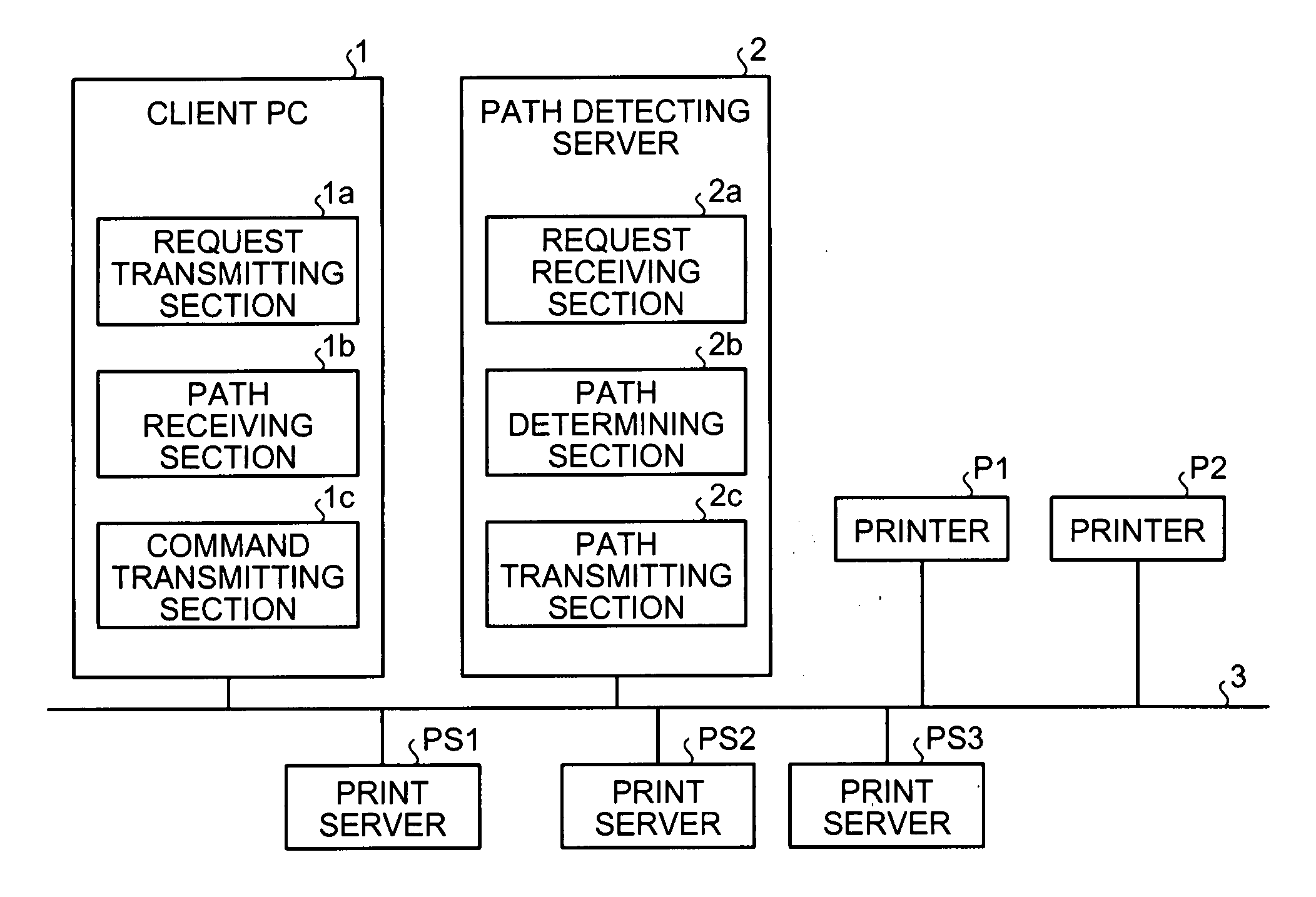
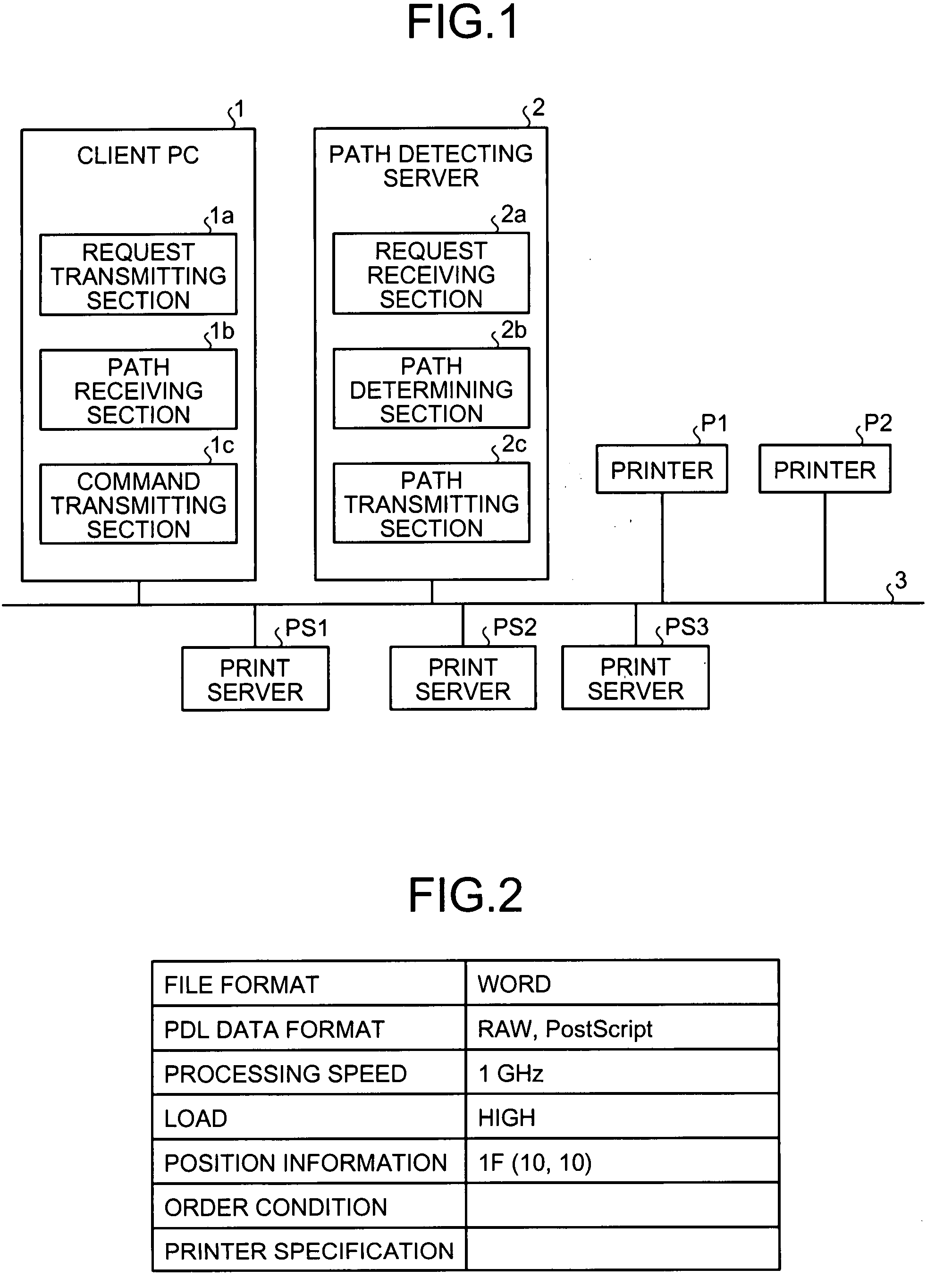
[0031]FIG. 1 is a block diagram of a print processing system according to the present invention. The print processing system includes a client personal computer (PC) 1, a path detecting server 2, printers P1 and P2, and print servers PS1, PS2, and PS3, all of which are connected to each other via a network 3. The network 3 can be a LAN, intranet, or the Internet. Hereinafter, when not needed to be distinguished, the printers P1 and P2 are indicated simply as printers P, and the print servers PS1, PS2, and PS3 are indicated simply as print servers PS. The number of the client PCs, the printers P, and the print servers PS is not limited to those shown in FIG. 1. Furthermore, each of the client PCs, printers P, and print servers PS includes, although not shown in the diagram, at least a central processing unit (CPU), a read only memory (ROM) that stores therein various programs and data, a random access memory (RAM), a communicating unit, and a bus that connects all these units to each...

second embodiment

[0078]In the second embodiment, the print server PS may transmit PDL data to another print server PS via the Web server 4. For example, through the print processing paths B′ and C′, the Web server 4 transmits print command data to the print server PS2. The print server PS2 then converts the print command data into PDL data, and transmits it to the Web server 4, not to the print server PS3. The Web server 4, when it receives these pieces of information, transmits to the printer server PS3 the information specifying the printer P1 and the PDL data according to the path information.

[0079]With the arrangement, as to the print processing paths B′ and C′, the print server PS2 may only have the function to convert print command data into PDL data and the function to transmit and receive data to and from the Web server. Further, the print server PS3 may only have the function to convert PDL data and the function to relay the PDL data to the printer P1. This allows use of a conventional prin...


PUM


Abstract

A client transmits a request, which requests a print processing path, to a path detecting server, and in response receives path information indicating a print processing path from the path detecting server. The client transmits the path information and PDL data to an apparatus subsequent to the client on the print processing path indicated in the path information. The path detecting server receives the request from the client and finds a print processing path referring to information of printers and print servers stored in an apparatus information database. A path detecting server transmits to the client path information indicating the print processing path.

Description

CROSS-REFERENCE TO RELATED APPLICATIONS[0001]The present application claims priority to and incorporates by reference the entire contents of Japanese priority documents, 2006-253288 filed in Japan on Sep. 19, 2006 and 2007-193878 filed in Japan on Jul. 25, 2007.BACKGROUND OF THE INVENTION[0002]1. Field of the Invention[0003]The present invention relates to a print processing system in which client devices, printers, and print servers are connected to each other via a network.[0004]2. Description of the Related Art[0005]Technologies are known that make it possible to select an optimal combination of a plurality of apparatuses to perform a printing process. Japanese Patent Application Laid-Open No. 2004-102613, for example, discloses a technology that makes it possible to determine, based on processing capabilities of the apparatuses and print job attributes indicating print conditions for performing the printing process, an optimal combination of printing apparatuses on which a print...

Claims


Application Information

Patent Timeline
IPC IPC(8): G06F3/12
CPCG06F3/1204G06F3/1214G06F3/1288G06F3/1226G06F3/122
Inventor EMORI, MOTOTSUGU
Owner RICOH KK
Why Eureka
Try Eureka