
Heat dissipating device holder structure with a thin film thermal conducting medium coating

a technology of thermal conducting medium and heat dissipating device, which is applied in the direction of semiconductor devices, semiconductor/solid-state device details, cooling/ventilation/heating modifications, etc., can solve the problems of the processor, affecting the heat dissipation effect of the heat dissipating device, and affecting the heat dissipation effect of the heat dissipation effect of the heat dis

Inactive Publication Date: 2008-03-20
CHEN SHYH MING
View PDF11 Cites 6 Cited by
  • Summary
  • Abstract
  • Description
  • Claims
  • Application Information

AI Technical Summary

Benefits of technology

"The present invention provides a heat dissipating device holder structure with a thin film thermal conducting medium coating that can effectively reduce the thermal conducting medium coating thickness of a heat sink holder and provide the best thin film coating, such that when a processor is attached, its thermal resistance can be lowered and its heat dissipation effect can be enhanced. The invention also reduces the consumption of thermal conducting medium, provides a more convenient use, and achieves a more precise, accurate and good connection with the processor."

Problems solved by technology

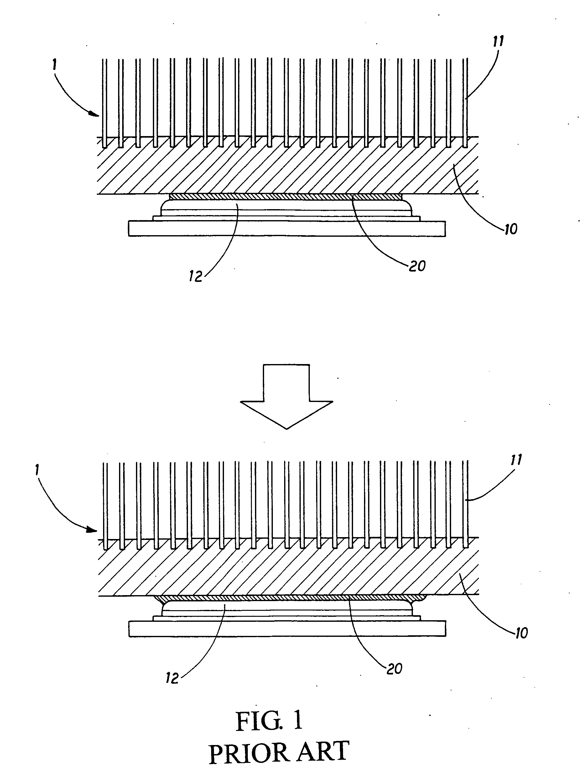
In general, the connection between the heat dissipating device and the processor cannot be achieved simply by connecting two planes, but it is necessary to coat a thermal conducting medium between the two planes.
Furthermore, the connecting force applied on the heat dissipating device holder 10 and the processor 12 is limited since the heat dissipating device holder 10 is fixed onto the processor 12, and thus an excessively large force applied onto the heat dissipating device holder 10 may damage the processor 12.
More specifically, the processor 12 may be damaged and the thermal conducting medium 20 may be squeezed out from the attaching surface incurring a waste, if the force applied on the thermal conducting medium 20 is too large.
Furthermore, the thermal conducting medium 20 is relatively expensive.
The excessively thick thermal conducting medium 20 will affect the heat conduction effect, or even produce a gap or result in a poor contact that will lower the heat dissipation efficiency.
An uneven or excessively thick coating of thermal conducting medium 20 cannot improve the heat conduction effect; on the contrary, it may even lower the heat conduction effect.

Method used


Image

  • Heat dissipating device holder structure with a thin film thermal conducting medium coating
  • Heat dissipating device holder structure with a thin film thermal conducting medium coating
  • Heat dissipating device holder structure with a thin film thermal conducting medium coating

Examples


Embodiment Construction

[0019]The above and other objects, features and advantages of the present invention will become apparent from the following detailed description taken with the accompanying drawing.

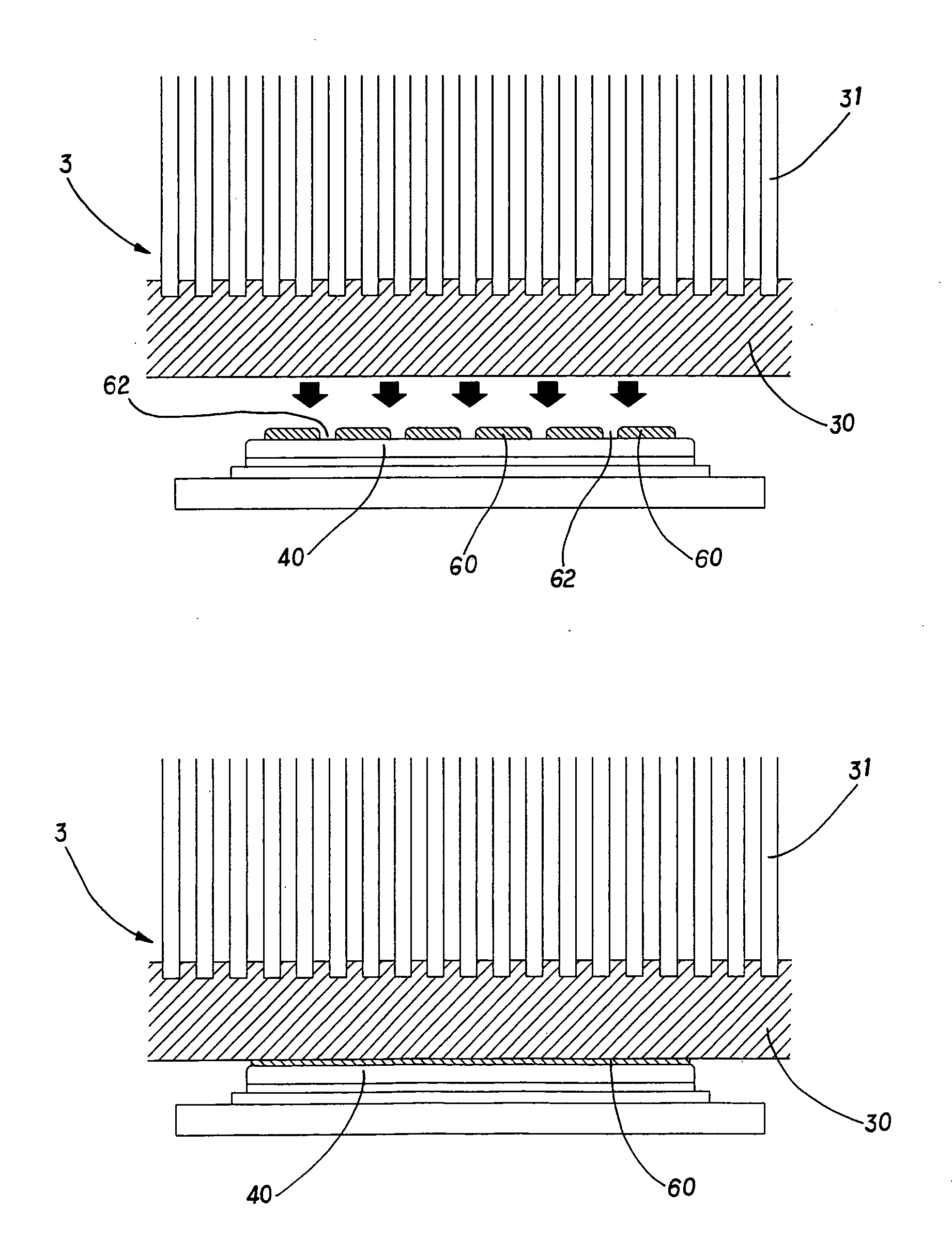
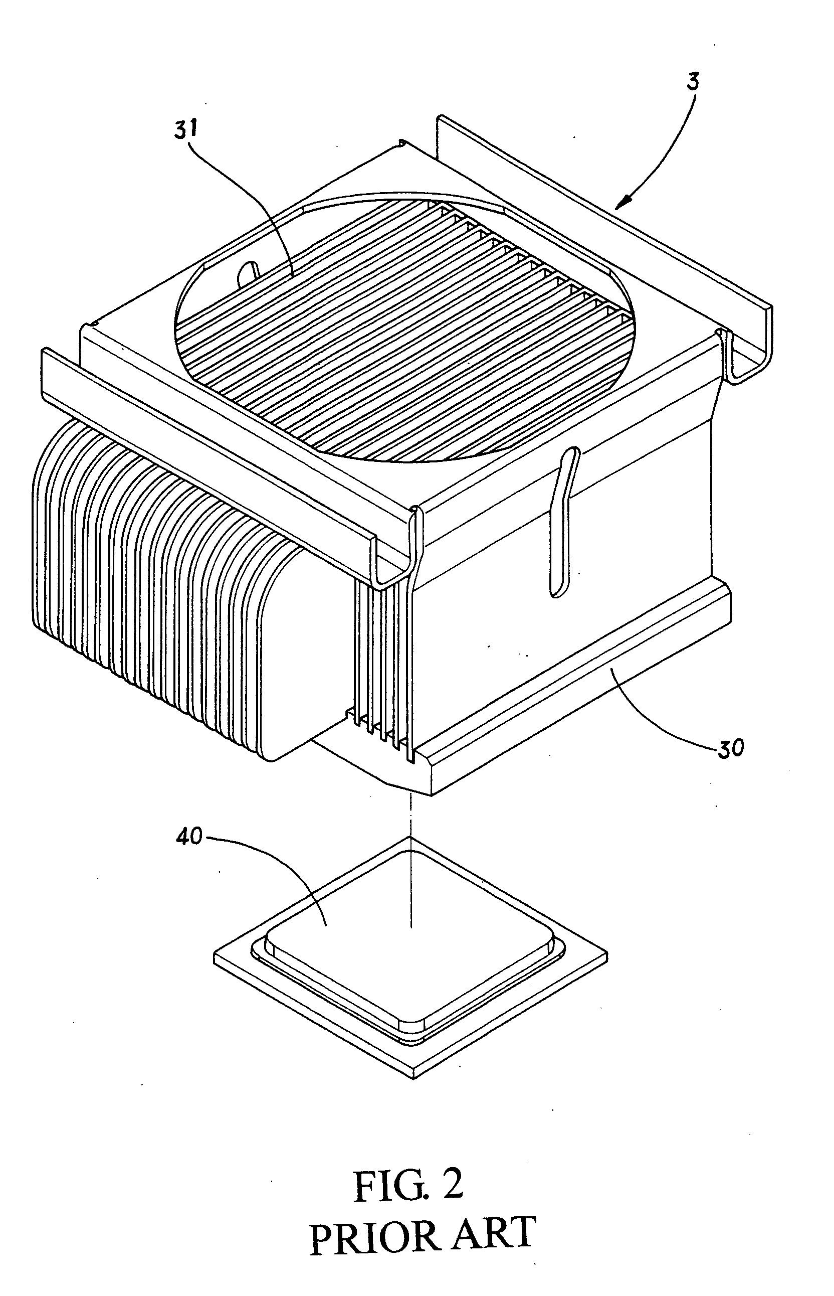
[0020]Referring to FIG. 2, a heat dissipating device 3 comprises a holder 30 and a plurality of fins 31 erected from an upper surface of the holder 30, and processor 40 disposed under the holder 30 of the heat dissipating device 3, and the processor 40 could be a central processing unit (CPU), a graphic processing unit (GPU) or any other chipset that will generate a great deal of heat during their operation.

[0021]Referring to FIG. 3 for a first preferred embodiment of the present invention, a basic type of a heat dissipating hold structure is illustrated. A plurality of thermal conducting medium coating blocks 50 are disposed on a lower surface of the holder 30, and its related layout is set, wherein at least two thermal conducting medium coating blocks 50 are disposed on the corresponding attaching surfa...


PUM


Abstract

In a heat dissipating device holder structure with a thin film thermal conducting medium coating, at least two thermal conducting medium coating blocks are set on attaching surfaces of a heat dissipating device holder and a processor, and a gap is disposed between the coating blocks, such that when the heat dissipating device holder is attached to the processor, the compressing force of the heat dissipating device holder and the processor exerted onto the thermal conducting medium coating blocks can be spread to fill the spread thermal conducting medium into a short distance of the gap, so as to achieve the best thin film coating for the thermal conducting medium and effectively lower thermal resistance and attach the heat dissipating apparatus holder tightly with the processor for the best heat dissipation effect.

Description

BACKGROUND OF THE INVENTION[0001]1. Field of the Invention[0002]The present invention relates to a heat dissipating device holder structure with a thin film thermal conducting medium coating, and more particularly to a heat dissipating device holder structure that attaches at least two thermal conducting medium coating blocks onto an attaching surface of a heat dissipating device holder to form the best thin film that is coated on a heat generating electronic component such as a processor or a chipset, and the thermal conducting medium coating blocks are attached tightly onto the attaching surface to effectively lower the thermal resistance and enhance the heat dissipation effect.[0003]2. Description of the Related Art[0004]Regardless of a high-speed computing processor or a high-end graphic processing chipset, the heat produced by such components become increasingly higher as the clock gets faster and faster. The commonest heat dissipation method adopts a heat dissipating device co...

Claims


Application Information

Patent Timeline
Patent Type & Authority Applications(United States)
IPC IPC(8): H05K7/20
CPCH01L23/42H01L23/467H01L2924/0002H01L2924/00
Inventor CHEN, SHYH-MING
Owner CHEN SHYH MING
Learn More