Optical disk apparatus
- Summary
- Abstract
- Description
- Claims
- Application Information
AI Technical Summary
Benefits of technology
Problems solved by technology
Method used
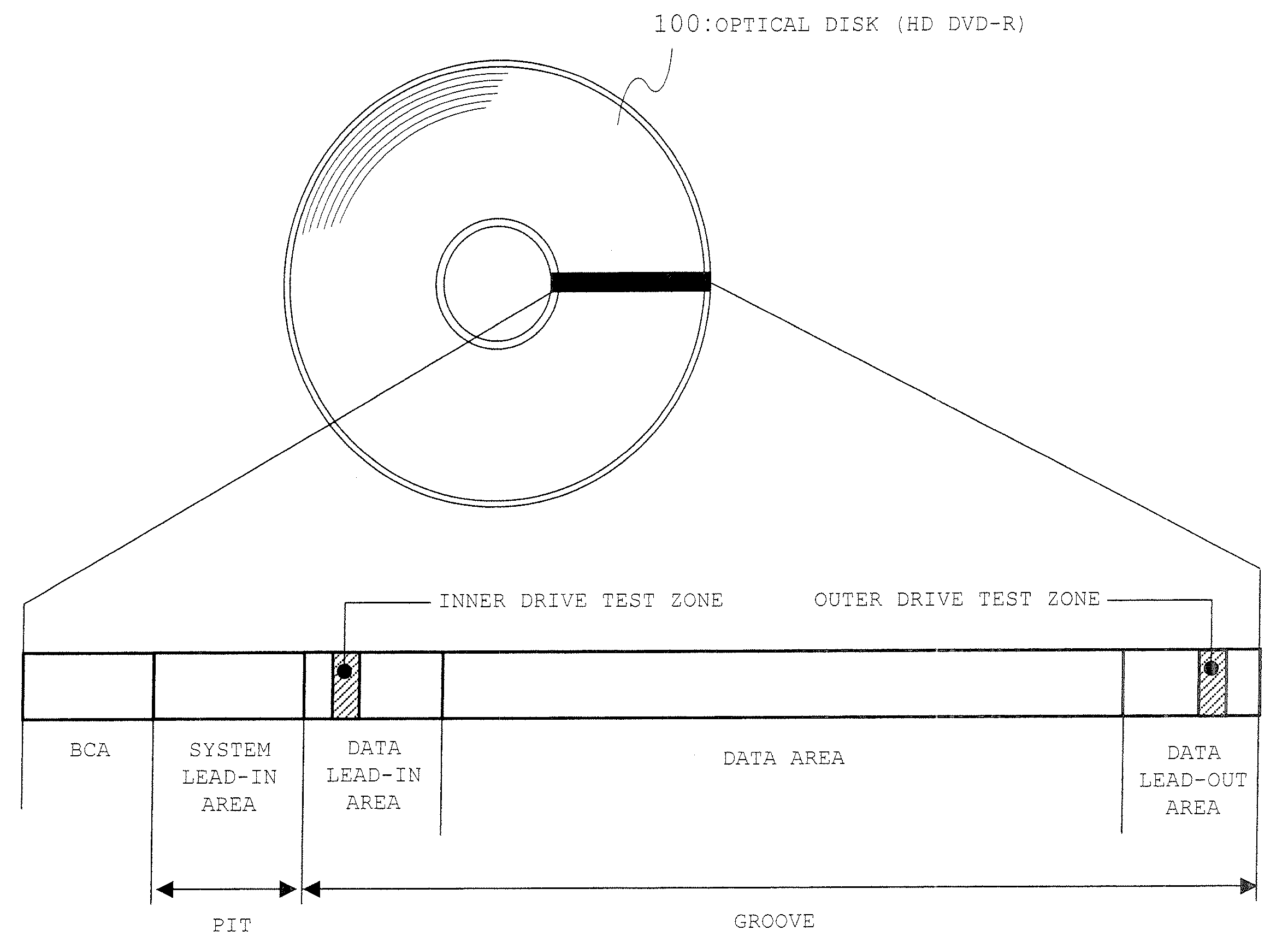
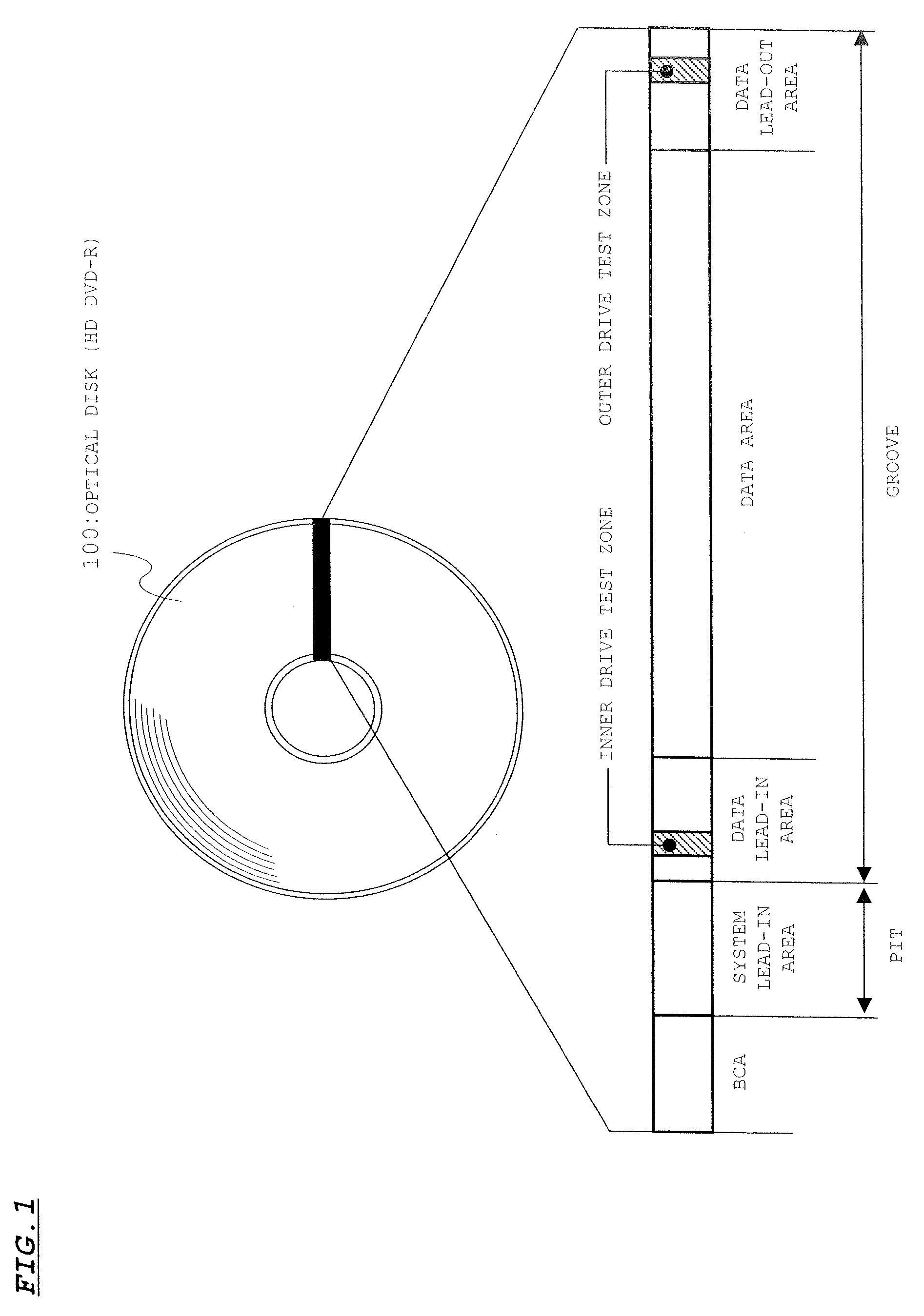
Image

Examples
first embodiment
[0048]A recording power setting method will be described with reference to FIGS. 3A and 3B.
[0049]FIG. 3A show measurement result when a track was reproduce to measure PRSNR after the recording is performed in a track (groove) on a sample disk (Low-to-High type HD DVD-R). A vertical axis indicates a recording laser power and a horizontal axis indicates PRSNR.
[0050]In the measurement, the track was irradiated with the laser beam with the laser power at each plotted point, and the recording was performed to the track. The PRSNR measurement was performed with an optical disk drive evaluation unit (type ODU-1000) produced by Plustec Industrial Co., Ltd. In the measurement, a disk linear velocity was set to 6.61 m / s (constant), and a reproduction laser power was set to 0.4 mW.
[0051]In the conventional recording power setting method, a recording power Pw is set to the power at which PRSNR becomes the maximum. In the measurement example of FIG. 3A, the recording power Pw was set to about 9....
second embodiment
[0083]A recording power setting method according to a second embodiment of the present invention will be described below with reference to FIGS. 7A to 7D.
[0084]FIGS. 7A and 7B show reproduction RF signals when the recording is performed to the same Low-to-High type HD DVD-R with recording powers Pw1 and Pw2 (Pw2>Pw1) respectively. As shown in FIGS. 7A and 7B, in the Low-to-High type HD DVD-R, a reproduction RF signal level rises with the degradation of the recording film property. Accordingly, an evaluation whether or not the recording power is proper can be made based on the reproduction RF signal level. That is, when the reproduction RF signal level exceeds a predetermined threshold level, it is evaluated that the recording power is excessive. When the reproduction RF signal level is not more than the threshold level, it is evaluated that the recording power is proper.
[0085]In the second embodiment, the reproduction RF signal obtained in reproducing the system lead-in area (pit fo...
PUM
 Abstract
Description
Claims
Application Information
 - Generate Ideas
- Intellectual Property
- Life Sciences
- Materials
- Tech Scout
- Unparalleled Data Quality
- Higher Quality Content
- 60% Fewer Hallucinations
Browse by: Latest US Patents, China's latest patents, Technical Efficacy Thesaurus, Application Domain, Technology Topic, Popular Technical Reports.
© 2025 PatSnap. All rights reserved.Legal|Privacy policy|Modern Slavery Act Transparency Statement|Sitemap|About US| Contact US: help@patsnap.com