Printing device and logic packet processing method

a logic packet and printing device technology, applied in the direction of digital output to print units, data switching networks, instruments, etc., can solve the problems of high load status of microprocessors, long time for printing process, and inability to perform printing process

Inactive Publication Date: 2008-03-20
SEIKO EPSON CORP
View PDF4 Cites 28 Cited by
  • Summary
  • Abstract
  • Description
  • Claims
  • Application Information

AI Technical Summary

Benefits of technology

[0006]An advantage of some aspects of the invention is that it provides a technology for suppressing a microprocessor used in a printing process from becoming a high load status in a printing device for transmitting / receiving a logic packet to / from a client.
[0008]In the printing device, since the plural types of logic packets are sorted into the logic packet to be processed by the hardware packet processing unit and the logic packet to be processed by the software packet processing unit, it is possible to reduce load of the software packet processing unit compared with a configuration in which all the logic packets are processed by the software packet processing unit. Accordingly, it is possible to suppress the microprocessor included in the software packet processing unit from becoming a high load status.
[0010]By this configuration, since the logic packet which requires a reply to the client to cause high processing load is processed by the hardware packet processing unit, it is possible to reduce the processing load of the microprocessor.
[0012]By this configuration, since the credit request packet which is frequently transmitted / received in order to control the flow is processed by the hardware packet processing unit, it is possible to remarkably reduce the processing load of the microprocessor.
[0014]By this configuration, when the printing process is performed in the high quality print mode, the processing load of the microprocessor is increased in order to a large amount of print data. However, since the credit request packet for transmitting the print data used in the printing process can be processed by the hardware, it is possible to suppress the microprocessor from becoming a very high load status.

Problems solved by technology

In such a configuration, if a processing load of the logic packet is increased due to the frequent reception of the logic packet from the client, the microprocessor is in a high load status and thus the printing process becomes stagnant.
Thus, it is take much time to perform the printing process.

Method used


Image

  • Printing device and logic packet processing method
  • Printing device and logic packet processing method
  • Printing device and logic packet processing method

Examples


first embodiment

A. First Embodiment

B. Second Embodiment

C. Third Embodiment

D. Modified Example

A. First Embodiment

A1. Schematic Configuration of Printing Device

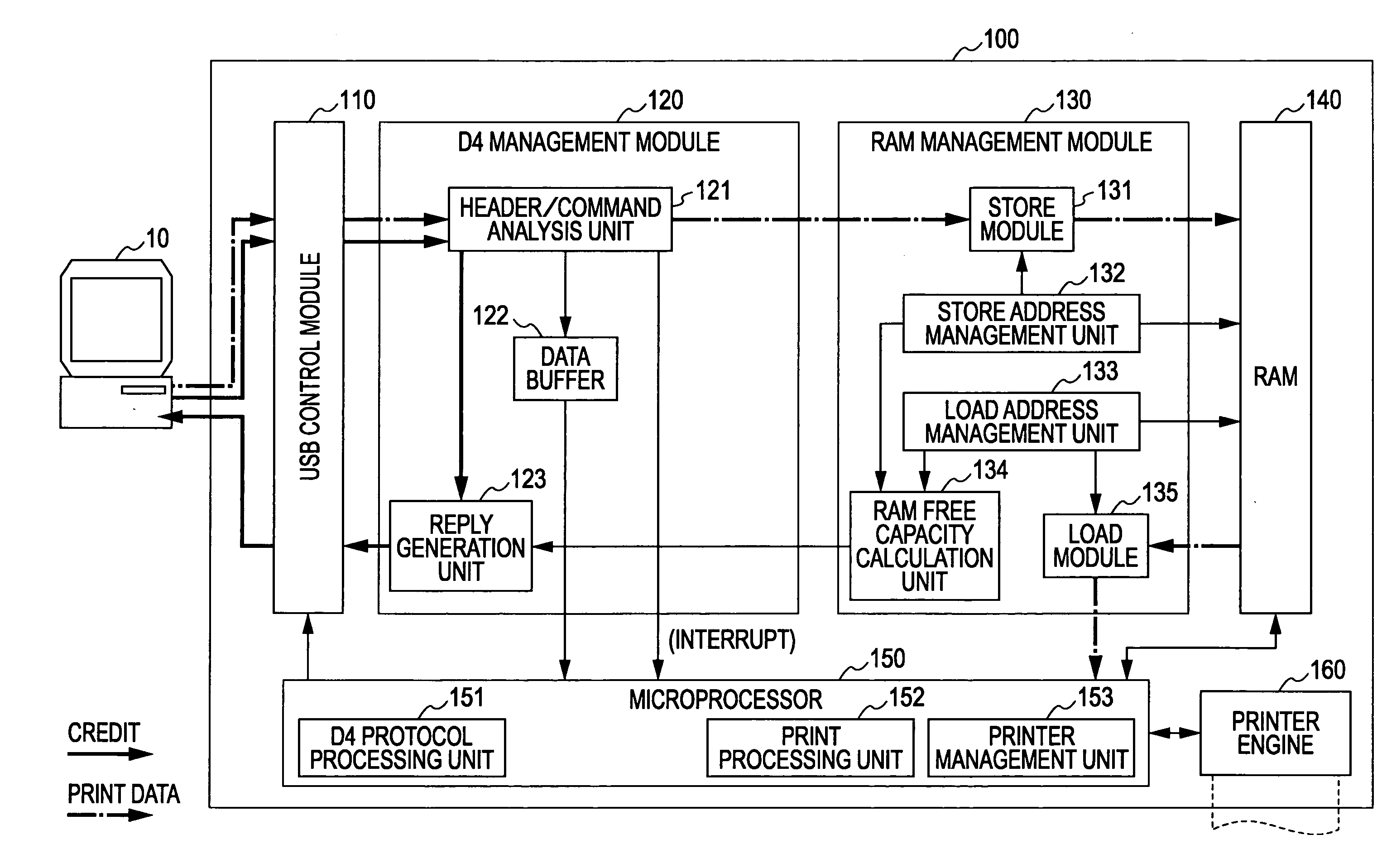
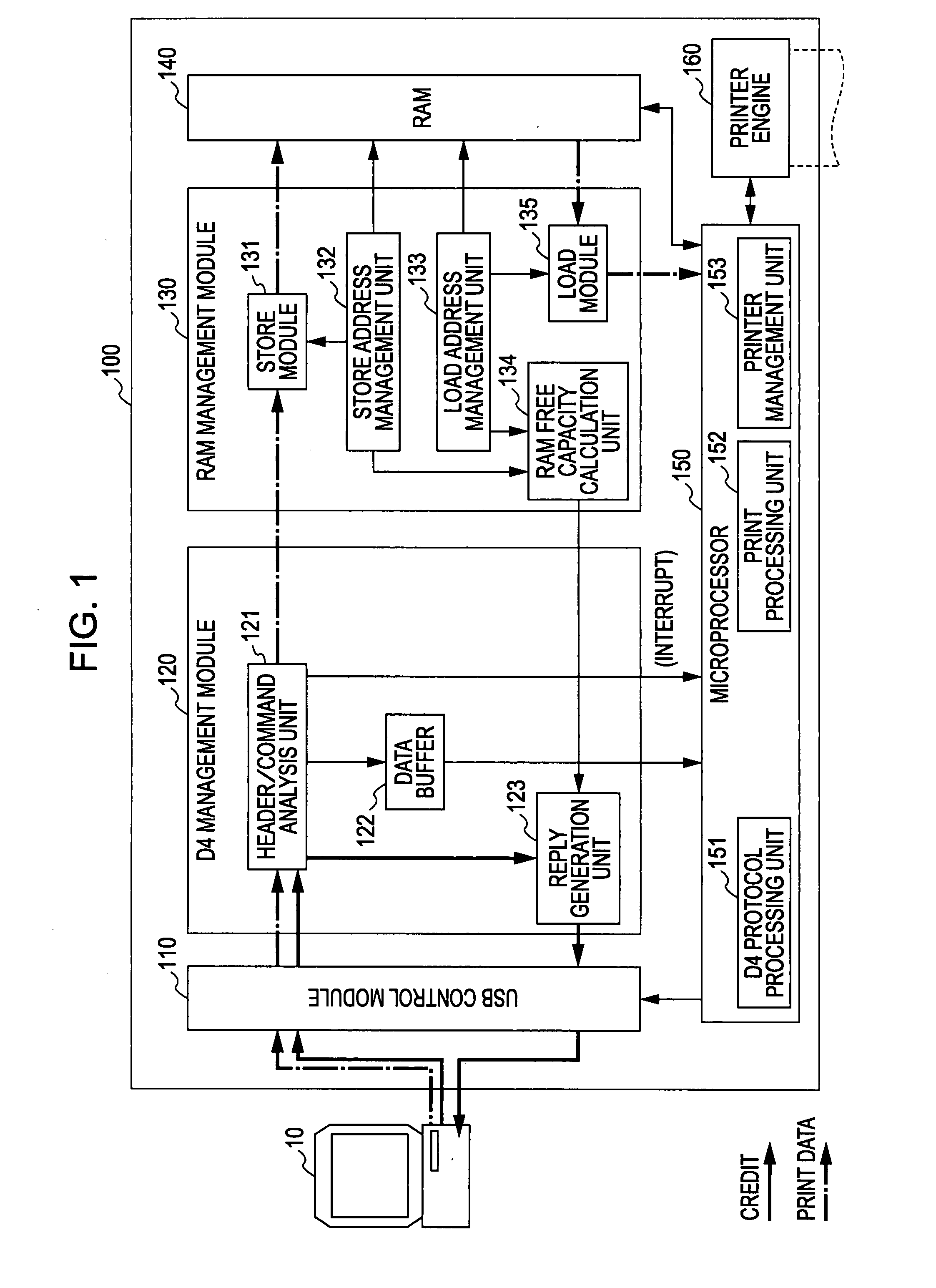
[0034]FIG. 1 is a schematic block diagram showing the configuration of a printer 100 according to a first embodiment of the invention. The printer 100 includes a USB control module 110, a D4 management module 120, a RAM management module 130, a RAM 140, a microprocessor 150 and a printer engine 160. The USB control module 110 includes a physical interface for connecting the printer 100 to a personal computer 10 through a USB and analyzes a USB protocol such that the printer 100 functions as a USB device. The D4 management module 120 sorts a D4 packet received from the personal computer 10 and performs a predetermined process according to a D4 protocol with respect to a specific type of D4 packet (credit request packet). The RAM management module 130 writes data to the RAM 140, reads data from the RAM 140, or manages a write address / read addres...

second embodiment

B. Second Embodiment

[0062]FIG. 6 is a schematic block diagram showing the configuration of a printer according to a second embodiment of the invention. The printer 101 is equal to the printer 100 shown in FIG. 1 except that a mode specifying value register 124 is included in the D4 management module. In the printer 100 according to the first embodiment, the D4 packet received from the personal computer 10 is sorted into the packet to be processed by the hardware (the credit request packet and the print data packet) and the packet to be processed by the software (the other packet) and is processed. In contrast, in the printer 101 according to the second embodiment, a mode for sorting and processing the D4 packet (sort processing mode) and a mode for processing all the D4 packets by the software (software processing mode) are set and are switched to process the D4 packet. The sort processing mode corresponds to a first processing mode and the software processing mode corresponds to a ...

third embodiment

C. Third Embodiment

[0067]FIG. 9 is a schematic block diagram showing the configuration of a printer according to a third embodiment of the invention. The printer 102 is equal to the printer 100 shown in FIG. 1 except that a credit number acquiring method specifying value register 125 is included in the D4 management module. In the second embodiment, the processing mode of the printer 101 is switched to the sort processing mode or the software processing mode such that the credit number according to the operation status of the printer 101 is notified to the personal computer 10. In contrast, in the third embodiment, only the sort processing mode is used as the processing mode and the credit number according to the operation status of the printer 102 is notified to the personal computer 10.

[0068]In the printer 102, as a method of obtaining the credit number by the reply generation unit 123 includes a method of calculating the credit number on the basis of the free capacity of the RAM ...


PUM


Abstract

Disclosed herein is a printing device connected to a client, the printing device including: a reception unit which receives plural types of logic packets from the client; a hardware packet processing unit which processes the logic packets by hardware; a software packet processing unit which includes a microprocessor and processes the logic packets by software; and a sorting unit which sorts the plural types of logic packets into a logic packet to be processed by the hardware packet processing unit and a logic packet to be processed by the software packet processing unit, wherein the sorting unit sorts a reply requiring logic packet including contents replying to the client as the logic packet to be processed by the hardware packet processing unit when sorting the plural types of logic packets.

Description

The entire disclosure of Japanese Patent Application No. 2006-253094, filed Sep. 19, 2006 is expressly incorporated by reference herein.BACKGROUND[0001]1. Technical Field[0002]The present invention relates to a technology for suppressing a microprocessor used in a printing process from becoming a high load status in a printing device.[0003]2. Related Art[0004]In a printing system in which a client (a personal computer or the like) is connected to a printing device, data communication between the client and the printing device has been performed by transmitting / receiving a logic packet. For example, a printing system in which a client is connected to a printer through a universal serial bus (USB), print data or a control command is transmitted / received by means of a logic packet defined by a D4 protocol (hereinafter, referred to as a “D4 packet”). The D4 protocol is a communication protocol defined by the IEEE 1284.4. Examples of a system for transmitting / receiving print data or a co...

Claims


Application Information

Patent Timeline
Patent Type & Authority Applications(United States)
IPC IPC(8): H04L12/56B41J29/38G06F3/12G06F13/00
CPCH04L47/10G06F9/505
Inventor MOTEGI, TSUTOMU
Owner SEIKO EPSON CORP
Why Eureka
Try Eureka