Irrigated ablation electrode assembly and method for control of temperature

a technology of irrigated ablation and electrodes, which is applied in the field of ablation electrode assemblies, can solve the problems of affecting the ability to accurately monitor and/or control the temperature of the ablation assembly, rendering accurate monitoring and control of the ablative process more difficult, etc., to achieve better monitoring of rising temperature, improve temperature control and/or monitoring, and minimize coagulation and unwanted tissue damage

Active Publication Date: 2008-03-20
ST JUDE MEDICAL ATRIAL FIBRILLATION DIV
View PDF7 Cites 86 Cited by
  • Summary
  • Abstract
  • Description
  • Claims
  • Application Information

AI Technical Summary

Benefits of technology

[0018] A technical advantage of the present invention is that the electrode assembly thermally separates the cooling irrigation fluid from the distal electrode, as well as from the temperature sensing mechanism(s) within the distal member, thereby allowing for improved temperature control and / or monitoring while simultaneously allowing for irrigation of the target areas to minimize coagulation and unwanted tissue damage. The separation of the cooling fluid from the temperature sensing mechanisms further allows for better monitoring of rising temperature of the electrode assembly during operation, as well as other tell-tale factors of over-ablation of targeted tissue areas.
[0019] The foregoing and other aspects, features, details, utilities, and advantages of the present invention will be apparent from reading the following description and claims, and from reviewing the accompanying drawings.

Problems solved by technology

However, introduction of this irrigation solution may inhibit the ability to accurately monitor and / or control the temperature of the ablation assembly during use.
This direct flow through the distal electrode tip lowers the temperature of the distal tip during operation, rendering accurate monitoring and control of the ablative process more difficult.

Method used


Image

  • Irrigated ablation electrode assembly and method for control of temperature
  • Irrigated ablation electrode assembly and method for control of temperature
  • Irrigated ablation electrode assembly and method for control of temperature

Examples


Embodiment Construction

[0027] In general, the instant invention relates to irrigated ablation electrode assemblies, and to methods of manufacturing and using such irrigated ablation electrode assemblies. For purposes of this description, similar aspects among the various embodiments described herein will be referred to by the same reference number. As will be appreciated, however, the structure of the various aspects may be different among the various embodiments.

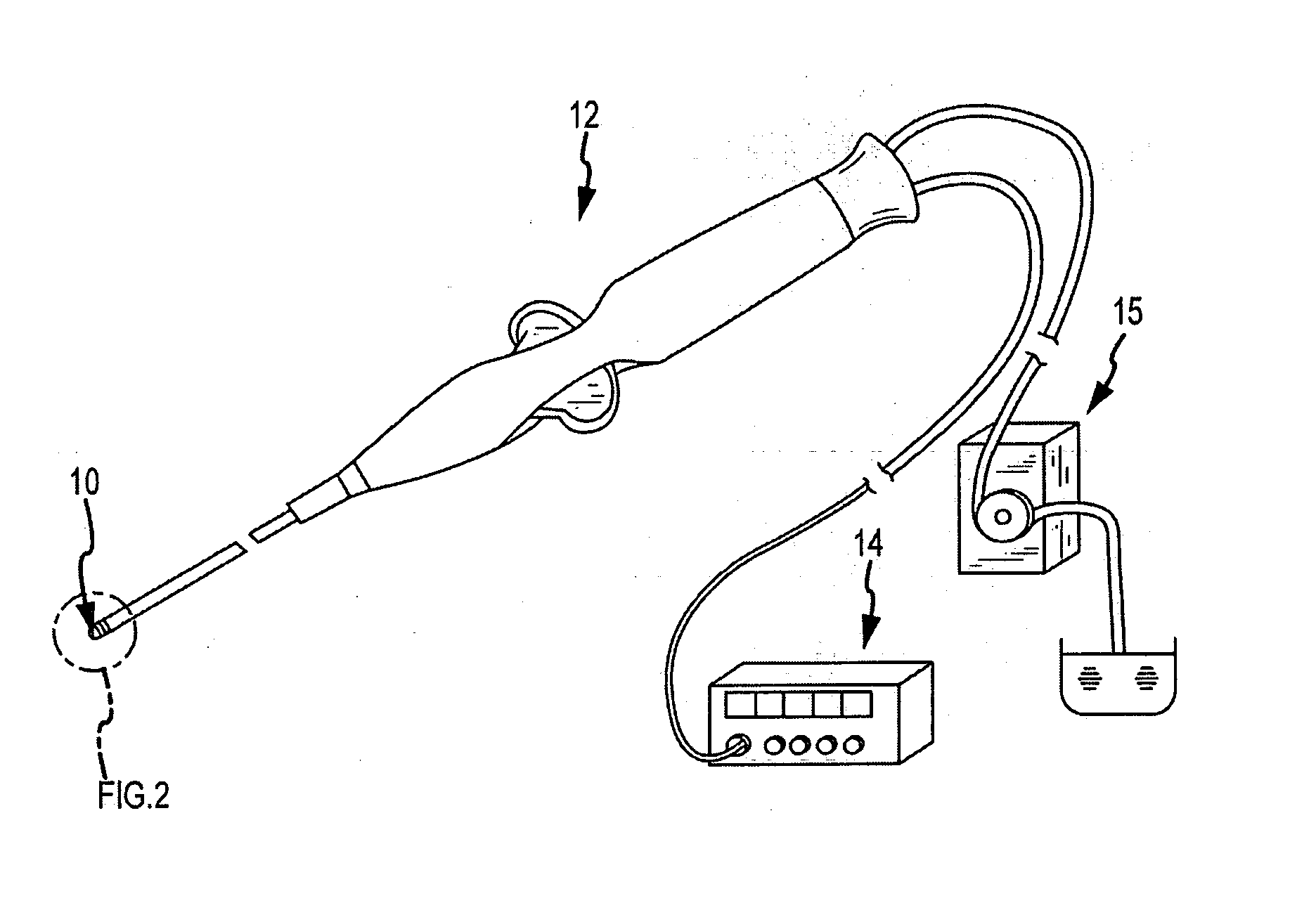
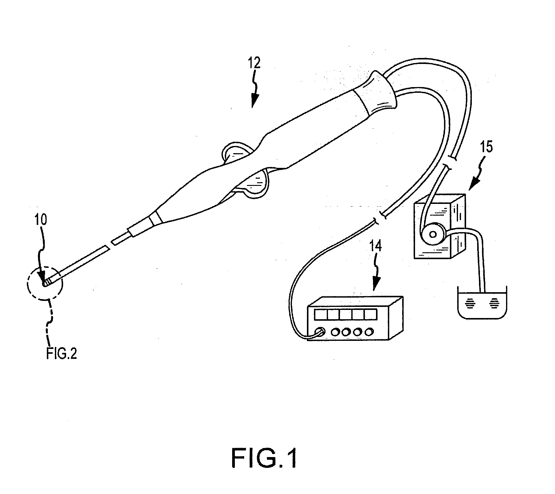
[0028] As seen in FIG. 1, the ablation electrode assembly may comprise part of an irrigated ablation catheter 12 assembly, operably connected to a pump assembly 15 and an RF generator assembly 14 which serves to facilitate the operation of ablation procedures through monitoring any number of chosen variables (e.g., temperature of the ablation electrode, ablation energy, and position of the assembly), assist in manipulation of the assembly during use, and provide the requisite energy source delivered to the electrode assembly 10. The present embo...


PUM


Abstract

Embodiments of the present invention provide an irrigated catheter having irrigation fluid directed at target areas where coagulation is more likely to occur so as to minimize blood coagulation and the associated problems. In one embodiment, an irrigated ablation electrode assembly for use with an irrigated catheter device comprises a proximal member having at least one passageway for a fluid with an outlet disposed at an external surface of the proximal member; and a distal member connected with the proximal member and having an external surface. The distal member includes an electrode. The external surface of the proximal member and the external surface of the distal member meet at an intersection. The at least one passageway of the proximal member is configured to direct a fluid flow through the outlet toward a region adjacent the intersection.

Description

CROSS-REFERENCE TO RELATED APPLICATIONS [0001] The present application is a continuation-in-part of U.S. patent application Ser. No. 11 / 434,200, filed May 16, 2006. This application is related to U.S. patent application Ser. Nos. 11 / 626,237, 11 / 626,255, 11 / 626,275, and 11 / 646,270, all filed on Dec. 28, 2006. The entire disclosures of the above applications are incorporated herein by reference.BACKGROUND OF THE INVENTION [0002] 1. Field of the Invention [0003] The present invention pertains generally to ablation electrode assemblies. More particularly, the present invention is directed toward ablation electrode assemblies for use in the human body having a mechanism for irrigating targeted areas. The present invention also relates to methods for improved assembly and accurate measurement and control of the electrode temperatures while effectively irrigating the targeted areas. [0004] 2. Background Art [0005] Electrophysiology catheters are used for an ever-growing number of procedure...

Claims


Application Information

Patent Timeline
Patent Type & Authority Applications(United States)
IPC IPC(8): A61B18/14
CPCA61B18/1492A61B2218/002A61B2018/00577A61B2017/00084
Inventor WANG, HUISUNDANDO, JEREMY D.PURYEAR, HARRY
Owner ST JUDE MEDICAL ATRIAL FIBRILLATION DIV
Why Eureka
Try Eureka