Wind Park with Robust Reactive Power Adjustment System and Method for the Operation Thereof

a reactive power adjustment and wind park technology, applied in the field of windparks, can solve the problems of inability to adjust the voltage and current of the lines and transformers in the windpark, the inability to control the voltage and current of the windpark, and the inability to disconnect individual wind energy installations, etc., to achieve robust windpark operational response, reduce the effect of power consumption

Active Publication Date: 2008-03-27
SIEMENS GAMESA RENEWABLE ENERGY SERVICE GMBH
View PDF2 Cites 61 Cited by
  • Summary
  • Abstract
  • Description
  • Claims
  • Application Information

AI Technical Summary

Benefits of technology

[0024] The linking point is expediently arranged on the high-voltage network, and is connected to the main line via a high-voltage transformer. This is a good approach for network connection, particularly for windparks with a high installed rating. However, it results in the disadvantage that high-voltage lines have a so-called natural rating for optimum operation because their capacitances are not negligible—in contrast to the situation with medium-voltage lines. Any discrepancies must be compensated for as appropriate by the wattless component. It is advantageous for the measurement point to be arranged on the high-voltage side of the transformer, for this purpose. However, this involves complex and expensive high-voltage measurement devices. It is therefore preferable for the measurement devices to be arranged on the main-line side of the high-voltage transformer. Provided that the transmission characteristics of the high-voltage transformer are known, this makes it possible to user lower-cost sensors.
[0025] The distributed regulator is preferably designed such that its control response has a time constant which is considerably longer than that of pulsed, short voltage fluctuations (voltage transients). This has the advantage that pulsed short voltage fluctuations have no influence on the regulator. Furthermore, this makes it possible to design the lower-level regulator such that it can react quickly to disturbances. This maintains a robust windpark operational response even in disturbed conditions.
[0026] In one proven embodiment, the distributed regulator has a limiting device for the nominal voltage. This ensures that excessively high nominal voltages do not cause any damage to the generator or its converter. This is particularly important for those wind energy installations which are connected to a relatively long connecting line. In this case, the complex impedance of the connecting line results in the voltage level not being the same as that of the parkmaster, and in particular it may be higher. Without limiting, damage could easily occur, and this is prevented by the limiting. The limiting device is expediently provided at each lower-level regulator. This allows improved individual matching to the individual wind energy installations. However, an arrangement can also be provided at the higher-level regulator.

Problems solved by technology

The installed power, which is therefore rising to a major extent, is currently leading to difficulties in the on-shore area where most windparks, and in particular large windparks, are located, owing to the restricted capacity of the power transmission network.
However, this results in a change in the voltages and currents on the lines and transformers in the windpark.
The known concepts have the disadvantage that, particularly in the case of wind energy installations which are located at the end of a long line in the windpark, undesirable voltage rises can occur, leading to instabilities.
This can result in undesirable disconnection of individual wind energy installations, or even damage to converters.

Method used


Image

  • Wind Park with Robust Reactive Power Adjustment System and Method for the Operation Thereof
  • Wind Park with Robust Reactive Power Adjustment System and Method for the Operation Thereof
  • Wind Park with Robust Reactive Power Adjustment System and Method for the Operation Thereof

Examples


Embodiment Construction

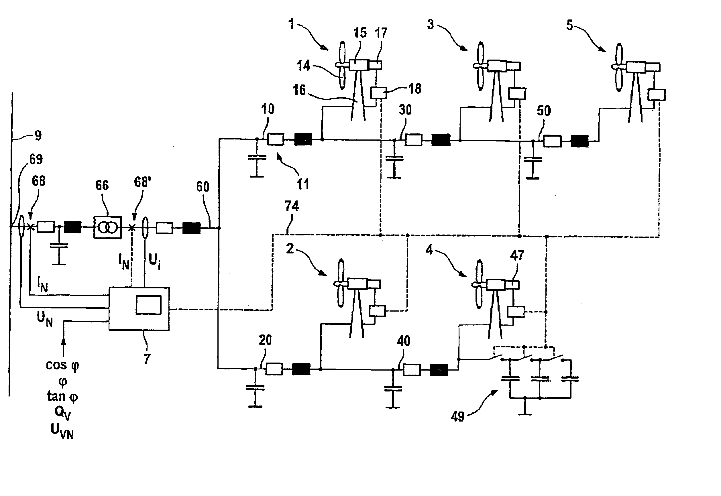
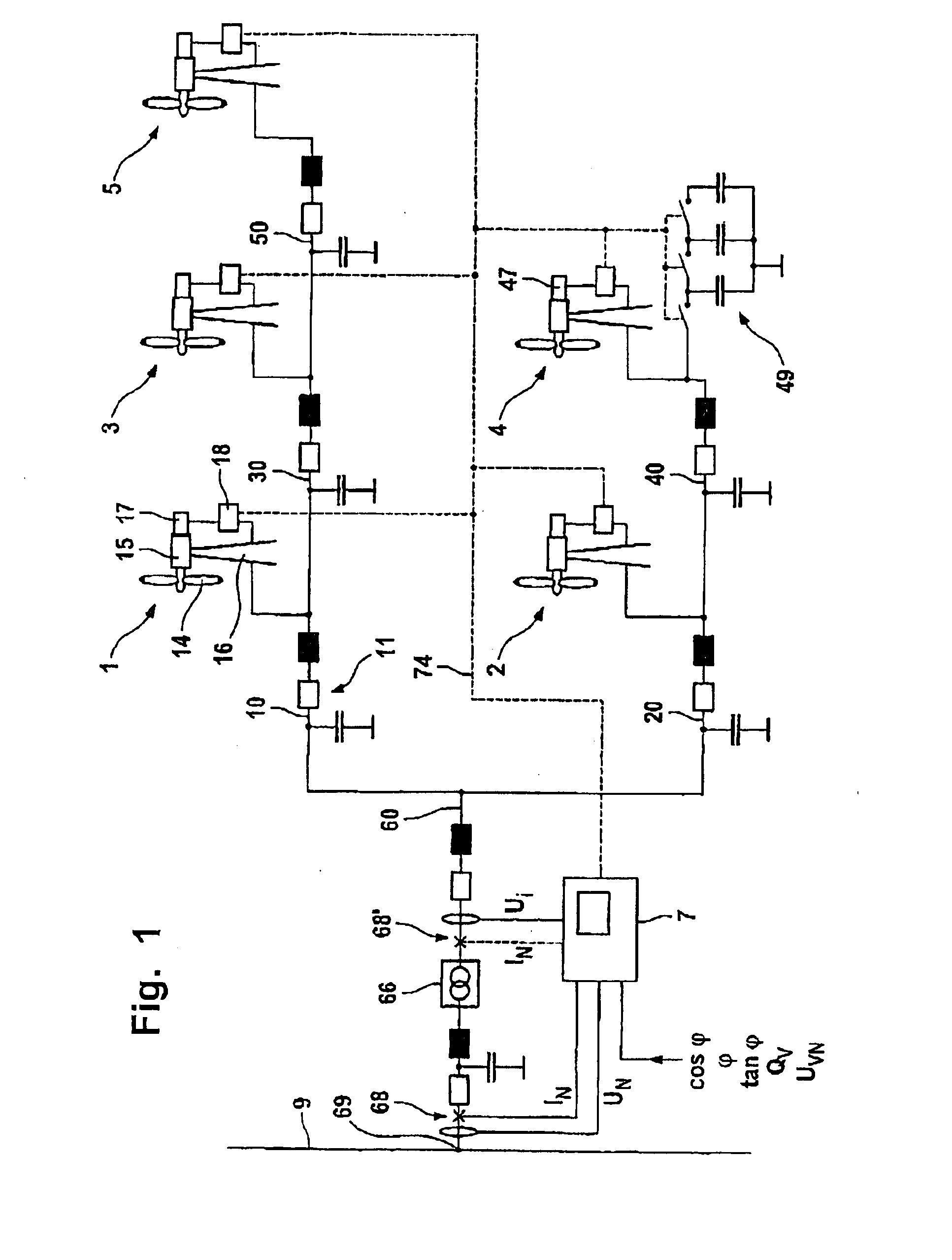
[0034]FIG. 1 illustrates one exemplary embodiment of a windpark according to the invention, which has a total of five wind energy installations (1-5) and one central host computer (parkmaster) 7 in the illustrated exemplary embodiment. The wind energy installations 1-5 are connected to one end of a main line 60 via connecting lines 10, 20, 30, 40, 50.

[0035] The design of the wind energy installations 1-5 will be explained using the wind energy installation 1 as an example. The wind energy installation 1 has a rotor 14 which is arranged on a machine housing 15 at the top of a tower 16 such that it can rotate. The rotor 14 drives a generator (not illustrated). This is preferably a double-fed asynchronous generator, although other types are also possible. The generator is connected to a converter 17, which converts the electrical power produced by the generator to three-phase electrical power at a fixed frequency (network frequency). The operation of the wind energy installation 1 is ...


PUM


Abstract

A windpark includes at least two wind energy installations, each of which installations comprises a rotor, a generator driven by the rotor and a control device, and which are connected via connecting lines to a main line. The windpark also includes a linking point which connects the main line to a power transmission network, a parkmaster which is configured for power factor control and has communication lines for transmission of control signals to the wind energy installations, and a power-factor control section including a distributed regulator having a higher-level regulator located at the parkmaster which is configured to determine a nominal voltage in order to set a global power coefficient for the power which is emitted to the power transmission network and to emit the global power coefficient as a signal via the communication lines and lower-level regulators at the wind energy installations.

Description

REFERENCE TO RELATED APPLICATIONS [0001] This application is a national stage filing under 35 USC 371 of International Application No. PCT / EP2005 / 010606, filed Sep. 30, 2005, which claims Convention priority from German Patent Application Nos. 10 2004 048 341.8, filed Oct. 1, 2004, the full disclosures of all of which are incorporated herein by reference. FIELD OF THE INVENTION [0002] The invention relates to a windpark having at least two wind energy installations, which each have a rotor, a generator driven by it and a control device, and which are connected via connecting lines to a main line, a linking point which connects the main line to a power transmission network and a parkmaster, which is designed for power factor control and has communication lines for transmission of control signals to the wind energy installations. The invention also relates to a method for operating such a windpark BACKGROUND OF THE INVENTION [0003] The development in the field of wind energy installat...

Claims


Application Information

Patent Timeline
Patent Type & Authority Applications(United States)
IPC IPC(8): H02P9/04F03D9/00
CPCF03D9/005H02J3/1885Y02E10/72Y02E40/32H02J3/386Y02E10/763F03D9/257H02J2300/28H02J3/381H02J3/46Y02E10/76Y02E40/30
Inventor FORTMANN, JENSLETAS, HEINZ-HERMANN
Owner SIEMENS GAMESA RENEWABLE ENERGY SERVICE GMBH
Why Eureka
Try Eureka