Routing for Microprocessor Busses

a microprocessor bus and buss technology, applied in the direction of logic circuits, semiconductor devices, pulse techniques, etc., can solve the problems of low performance of shared input/output implementation, inconvenient use, and inability to meet the needs of large-scale inputs,

Inactive Publication Date: 2008-03-27
HENDERSON ALEX
View PDF9 Cites 16 Cited by
  • Summary
  • Abstract
  • Description
  • Claims
  • Application Information

AI Technical Summary

Benefits of technology

[0094]Because the signals are part of a high fan-in function the OR functions in the routing blocks where the signals join are turned on. This allows the many signals that make up a the high fan-in OR in a large multiplexer to be routed using only the resources required for a single signal.

Problems solved by technology

These shared signal techniques require more complex drivers and special circuits like “active pull-ups” and “bus keepers”.
As a result the shared input / output implementation has fallen out of favor in FPGA and ASIC designs.
The implementation shown in FIG. 18 does not perform well for large numbers of inputs.
The serial chain of multiplexers limits the maximum speed of this implementation.
This performance comes at the cost of increased routing.
In the Xilinx and Altera designs the multiplexers also consume logic resources.
This also complicates the place and route process since the multiplexers must be placed in locations that have the least impact on timing and routing.
Optimal placement of the multiplexers and generation of control signals for the multiplexers in a multiplexer tree can be very complicated.
Routing of microprocessor, peripheral, and memory interconnections consumes a large portion of the routing resources and logic in FPGAs and structured ASIC devices.

Method used


Image

  • Routing for Microprocessor Busses
  • Routing for Microprocessor Busses
  • Routing for Microprocessor Busses

Examples


Embodiment Construction

[0115]FIG. 21: Conventional Multiplexer Tree in an FPGA

[0116]FIG. 22: Routing of Signals

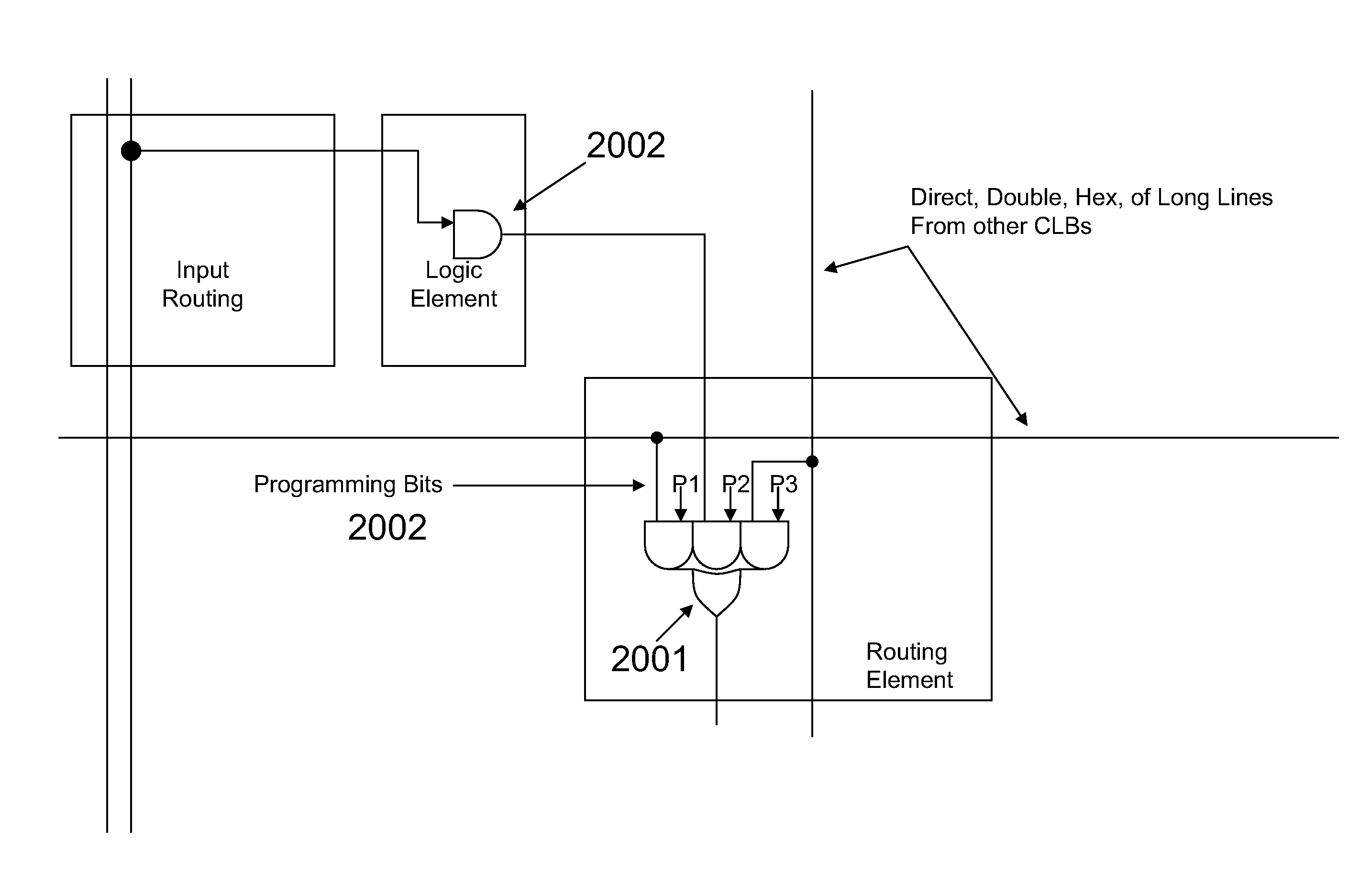
[0117]FIG. 23: The output AND function in a Xilinx like Logic Element

[0118]FIG. 24: Implementation of Routing Element

[0119]FIG. 25: RAM block with AND outputs

[0120]FIG. 26: Transfer Gated replaced by OR function with Repeaters

[0121]FIG. 27: An alternate embodiment incorporating the AND function in the output routing function

[0122]FIG. 28: Preferred Embodiment of a Microprocessor Peripheral in an FPGA

[0123]FIG. 29: Data Output Routing of Distributed RAM

[0124]FIG. 30: Logic Element Configuration for Efficient CAM Implementation

[0125]FIG. 31: Hierarchical Construction of a Large ASIC

[0126]FIG. 32: Routing Within a Hierarchical Block

DETAILED DESCRIPTION OF THE INVENTION AND THE PREFERRED EMBODIMENT

[0127]The preferred embodiment of the invention comprises the addition of an AND element and buffer to the output of the logic element of an FPGA, a routing element that utilized unidirectional signals and ...


PUM


Abstract

This invention provides means and methods for improving the routing and multiplexing logic of microprocessor busses and other similar high fan logic functions in FPGA and ASIC circuits. Routing of high fan-in signals is simplified by distributing the multiplexing function. The multiplexing function is separated into an AND function in the logic block and a programmable OR function in the routing block. Programming bits control which signals are ORed together in the routing elements. The AND output of a peripheral is controlled by either a distributed control circuit or by control signal(s) from a centralized control circuit.

Description

CROSS-REFERENCE TO RELATED APPLICATIONS[0001]Not Applicable.BACKGROUND OF THE INVENTION[0002](1) Field of the Invention[0003]The invention relates to programmable logic devices such as Field Programmable Gate Arrays (FPGA) and in particular, means and methods for improved routing of microprocessor busses.[0004]Overview[0005]Field Programmable Gate Arrays (FPGA) are configurable logic devices that can be tailored to a specific application. The configuration information may be stored in RAM bits, a persistent storage technology such as Flash memory bits, or a PROM technology such as fuses.[0006]FIG. 1 is a simplified block diagram that illustrates the difference between an FPGA and other programmable logic devices known in the related art. FPGAs incorporate logic elements (101) and routing resources. In this example, the routing resources comprise output routing elements (102), wires (103), and input routing elements (104). The input routing elements (104) provide programmable connect...

Claims


Application Information

Patent Timeline
Patent Type & Authority Applications(United States)
IPC IPC(8): H03K19/177
CPCH03K19/17736H03K19/17732
Inventor HENDERSON, ALEX
Owner HENDERSON ALEX
Why Eureka
Try Eureka