Video signal processing apparatus, video displaying apparatus and high resolution method for video signal

a video signal and processing apparatus technology, applied in the field of high-resolution video signals obtained from video signals, can solve the problem of only increasing the number of pixels, and achieve the effect of high-resolution video signals

Active Publication Date: 2008-03-27
MAXELL HLDG LTD
View PDF9 Cites 34 Cited by
  • Summary
  • Abstract
  • Description
  • Claims
  • Application Information

AI Technical Summary

Benefits of technology

[0011]As was mentioned above, when conducting an interpolation upon pixels through a wideband low-pass filter for transmitting the frequency band (frequency band from 0 to sampling frequency fs) being 2-times of the Nyquist frequency, by the wideband interpolation of the above (2), sum can be obtained of the component same to the original signal (hereinafter, being called “original component”) and the aliasing component depending on the sampling phase. In this instance, when conducting the wideband interpolation of the above (2) upon the signals of three (3) pieces of frame videos, as is shown in FIG. 3(a), it is well-known that all phases of the original components (301), (302) and (303) of each frame are coincident with one another, and that the phases of aliasing components (304), (305) and (306) rotate depending on the sampling phase of the each frame. For easy understanding of phase relationship between the respective ones, the phase relationship of the original components of the each frame is shown in FIG. 3(b), and the relationship of the aliasing components of the each frame in FIG. 3(c).
[0017]Also, it is possible to provide an auxiliary pixel interpolation means for increasing the video data of the input video frame through the interpolation, thereby outputting a result of that auxiliary pixel interpolation means, in the place of a result of removing the aliasing components mentioned above, when the above-mentioned coefficient cannot be determined, in the structures thereof.
[0018]Thus, according to the present invention, it is possible to achieve the high resolution of the video signals, in more preferable manner.

Problems solved by technology

In this instance, however, it is impossible to increase the resolution only by increasing the pixel number, through an interpolation low-pass filter using sinc function or spline function, being well-know in general.

Method used


Image

  • Video signal processing apparatus, video displaying apparatus and high resolution method for video signal
  • Video signal processing apparatus, video displaying apparatus and high resolution method for video signal
  • Video signal processing apparatus, video displaying apparatus and high resolution method for video signal

Examples


embodiment 1

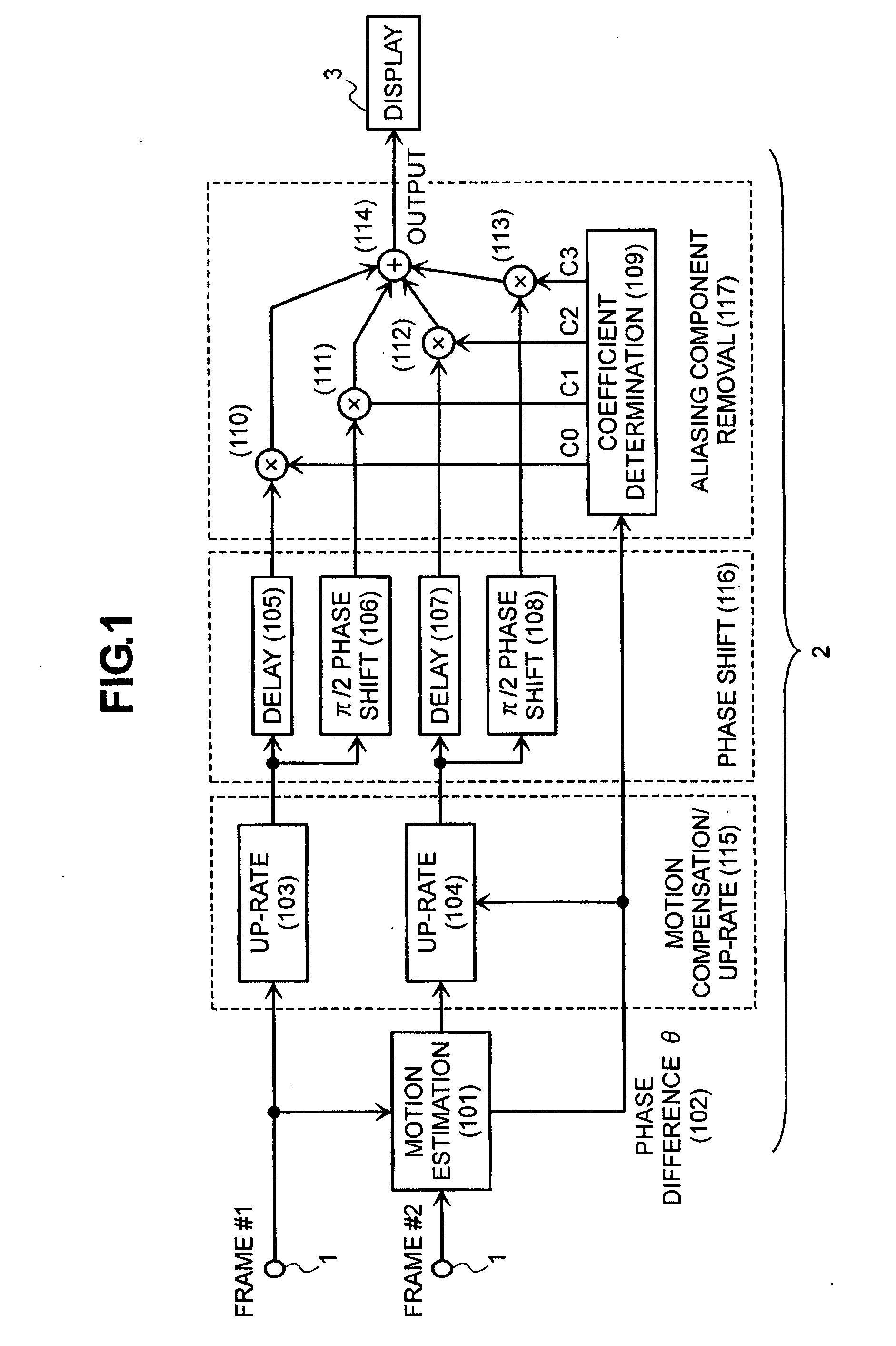
[0058]FIG. 1 shows a first embodiment of the video signal processing apparatus, according to the present invention, and the distinctive features thereof will be mentioned. The video signal processing apparatus, according to the present embodiment, will be applied into a video display apparatus, such as, a television receiver, etc., for example. In the present embodiment mentioned below, explanation will be made on the example of the video display apparatus, as the video signal processing apparatus. In FIG. 1, the video signal processing apparatus, according to the present embodiment, comprises an input portion 1, into which are inputted a frame line of moving pictures, such as, a television broadcast signal or the like, for example, a resolution converter portion 2 for obtaining high resolution of frames, which are inputted from that input portion, and further a display portion for displaying a picture upon basis of the frames, which are high resolved within that resolution converte...

embodiment 2

[0070]FIG. 10 shows a second embodiment according to the present invention. The structures shown in this figure are obtained by simplifying the structures shown in FIG. 1, with using the relationship among the coefficients C0, C1, C2 and C3 shown in FIG. 9(c). Thus, since C0=C2=½ and C1=−C3=−(1+cos θ) / 2 sin θ, the signals of sum and difference are produced by means of an adder (1001) and a subtractor (1004), from the frame #1 and the frame #2 after the motion compensation and up-rating. With the sum signal, after passing through a fs cut-off filter (1002), it is inputted into an adder (1008) with multiplying by C0 (=0.5) within a multiplier (1003). Herein, the fs cut-off filter (1002) is for cutting off the components of the sampling frequency (fs) before up-rating as a zero point, and it can be achieved by using the tap coefficients shown in (1011) of FIG. 10, for example. The propose of providing this fs cut-off filter (1002) lies to prevent unnecessary component of frequency fs f...

embodiment 3

[0072]FIG. 11 shows a third embodiment according to the present invention. The structures shown in this figure is constructed upon basis of the structures shown in FIG. 10, enabling to change an output from an auxiliary pixel compensation portion (1105) when the phase difference θ comes close to zero (0), for the purpose of preventing the coefficients C1 and C3 from becoming unstable when the phase difference θ is zero (0), as shown in FIG. 9(d), and / or preventing the coefficients C1 and C3 from becoming weak against noises due to becoming large as the phase difference θ comes close to zero (0). Thus, a general interpolation low-pass filter (1101) is prepared as a bypass route, while C4 is newly produced other than the above-mentioned coefficients C0 and C1 within the coefficient determining portion (1103), and an output of the interpolation low-pass filter (1101) is multiplied by the coefficient C4 within the multiplier (1102), and thereafter it is outputted after being added onto ...


PUM


Abstract

For providing a technology for preferably achieving high resolution of video signals of a video signal or moving video, with a small number of frames thereof, a video signal processing apparatus comprise an input unit to be inputted a plural number of video frames, a resolution converter unit, having resolution converting characteristics differing from each other, depending on a direction thereof, by composing 2 pieces of the video frames from the inputted video frames, thereby increasing a number of pixels making up the video frames, and a mixer unit for obtaining the output video frame by mixing output results of the resolution converter unit.

Description

BACKGROUND OF THE INVENTION[0001](1) Field of the Invention[0002]The present invention relates to a technology for obtaining a high-resolution video signal from a video signal, and in particular, it relates to a technology for achieving the high resolution, with increasing a number of pixels building up a video frame and removing unnecessary aliasing, while composing or combing a plural number of video frames.[0003](2) Description of the Related Art[0004]In recent years, advancement is made on large sizing of the screen, for television receivers, and accompanying with this, it is common that the video signal inputted from broadcasting, communication and / or storage medium, etc., is not displayed on it as it is, but is displayed with increasing the pixel numbers in the horizontal / vertical directions through digital signal processing. In this instance, however, it is impossible to increase the resolution only by increasing the pixel number, through an interpolation low-pass filter usin...

Claims


Application Information

Patent Timeline
IPC IPC(8): H04N7/01
CPCG06T3/4084H04N7/014H04N7/0125
Inventor KAGEYAMA, MASAHIROHAMADA, KOICHINAGAYA, SHIGEKI
Owner MAXELL HLDG LTD
Why Eureka
Try Eureka