Laser scanner

a laser scanner and laser technology, applied in the field of laser scanners, can solve the problems of inability to numerically recognize the direction in which the object to be measured is positioned with respect to the laser scanner, inability to avoid complicated procedures, and a large amount of time for acquiring images, etc., to achieve easy association, simple structure, and high working efficiency

Active Publication Date: 2008-03-27
KK TOPCON
View PDF6 Cites 22 Cited by
  • Summary
  • Abstract
  • Description
  • Claims
  • Application Information

AI Technical Summary

Benefits of technology

[0008]According to the present invention, a laser scanner comprises a mirror rotatably provided, a driving unit for rotating the mirror, a distance measuring unit for projecting a distance measuring light for scanning to a measurement range via the mirror and for obtaining a position data by receiving the reflected distance measuring light via the mirror, a measuring direction observing means for indicating a projecting direction of the distance measuring light, and an operation unit for setting the measurement range by designating at least two measuring directions based on the result of observation of the measuring direction obtained by the measuring direction observing means. As a result, the measurement range can be set up without using an external control device such as a PC. Also, the measurement range can be set up by continuously confirming the measuring direction, and this contributes to the achievement of higher working efficiency.
[0009]Also, according to the present invention, the measuring direction observing means is a sighting device mounted on the mirror. As a result, the system with simple structure can be attained, and the measuring direction can be easily associated with the result of observation on the measuring direction.
[0010]Further, according to the present invention, the sighting device comprises an optical path deflecting means for deflecting a collimating direction. This makes it possible to perform the collimation by the measurement operator regardless of the measuring direction.
[0011]Also, according to the present invention, the measuring direction observing means comprises a digital image pickup unit for acquiring image data via the mirror and a display unit for displaying the acquired image. This makes it possible to set the measurement range by the measurement operator regardless of the measuring direction.
[0012]Further, according to the present invention, the mirror can be rotated in a horizontal direction and in an elevation direction, and the laser scanner further comprises a horizontal angle detector for detecting a horizontal angle of the mirror and an elevation angle detector for detecting an elevation angle of the mirror, and the measuring direction is designated based on the horizontal angle detected by the horizontal angle detector and based on the elevation angle detected by the elevation angle detector. As a result, the measurement range can be set up by using the functions of the laser scanner, and this leads to simpler system construction.
[0013]Also, according to the present invention, the mirror can be rotated in a horizontal direction and in an elevation direction, and the laser scanner further comprises a horizontal angle detector for detecting a horizontal angle and an elevation angle detector for detecting an elevation angle, and the measuring direction is designated based on the horizontal angle detected by the horizontal angle detector and based on the elevation angle detected by the elevation angle detector, and also based on a position on the screen. As a result, the measurement range can be set up by using the functions of the laser scanner, and this leads to simpler system construction.

Problems solved by technology

In the case the measurement range is set up by inputting numerical values, an operator of the measurement cannot numerically recognize as to in which direction the object to be measured is positioned with respect to the laser scanner.
When the image is incorporated into the PC from the laser scanner, numerical values on a range to be incorporated must be set up again from the PC, and complicated procedures cannot be avoided.
In this respect, it is necessary to acquire an image, which is far wider and extensive than the measurement range itself, and this means that much time is needed for acquiring the image.

Method used


Image

  • Laser scanner
  • Laser scanner
  • Laser scanner

Examples


first embodiment

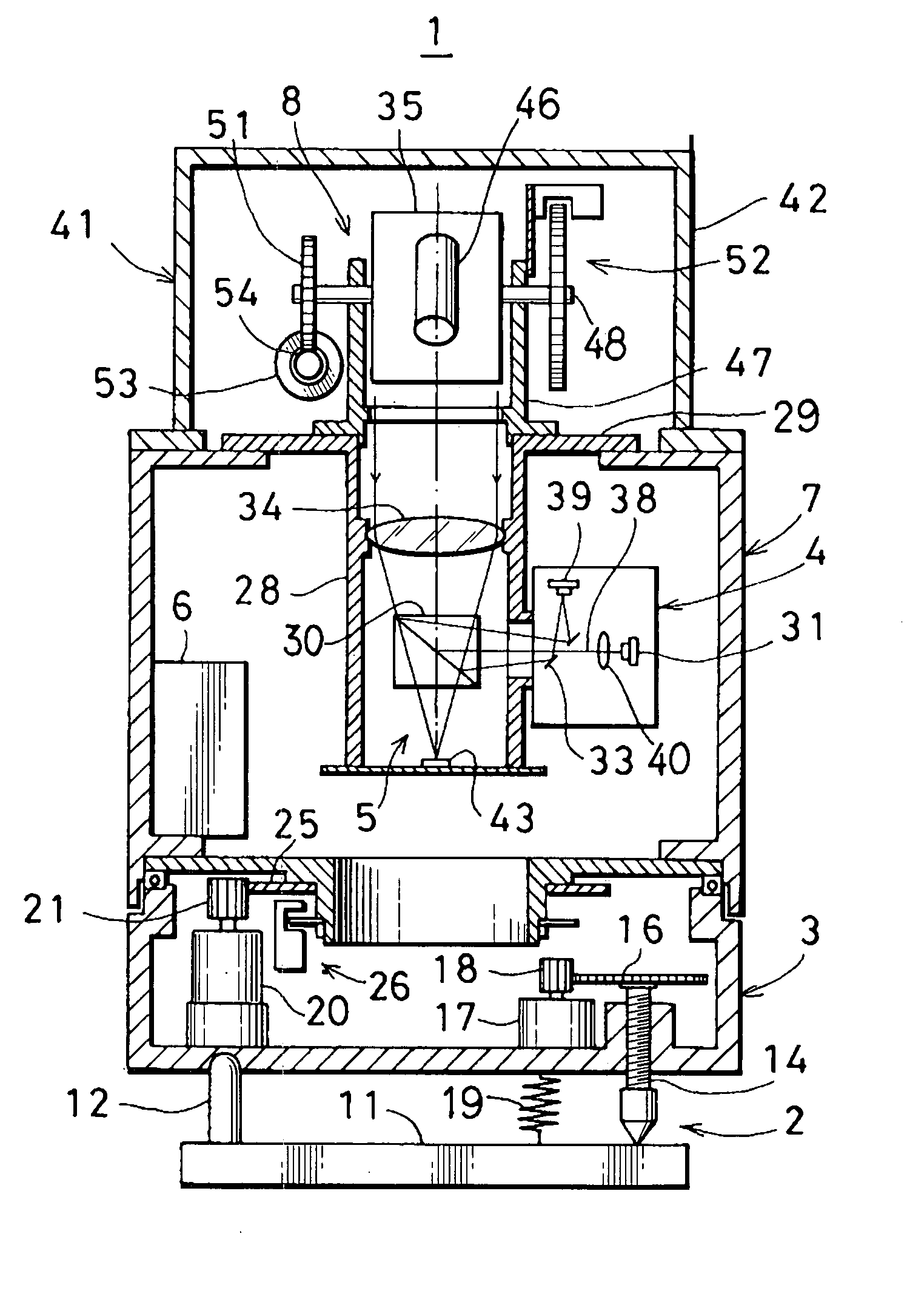
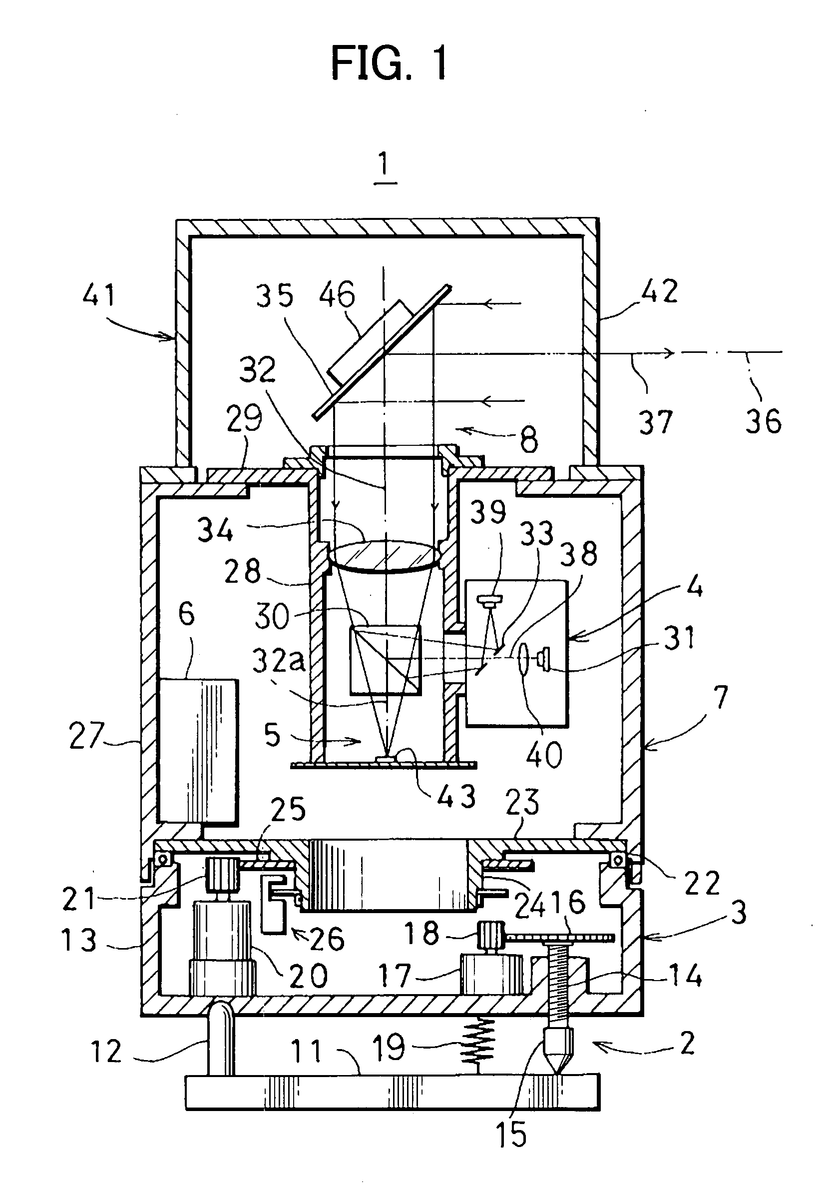
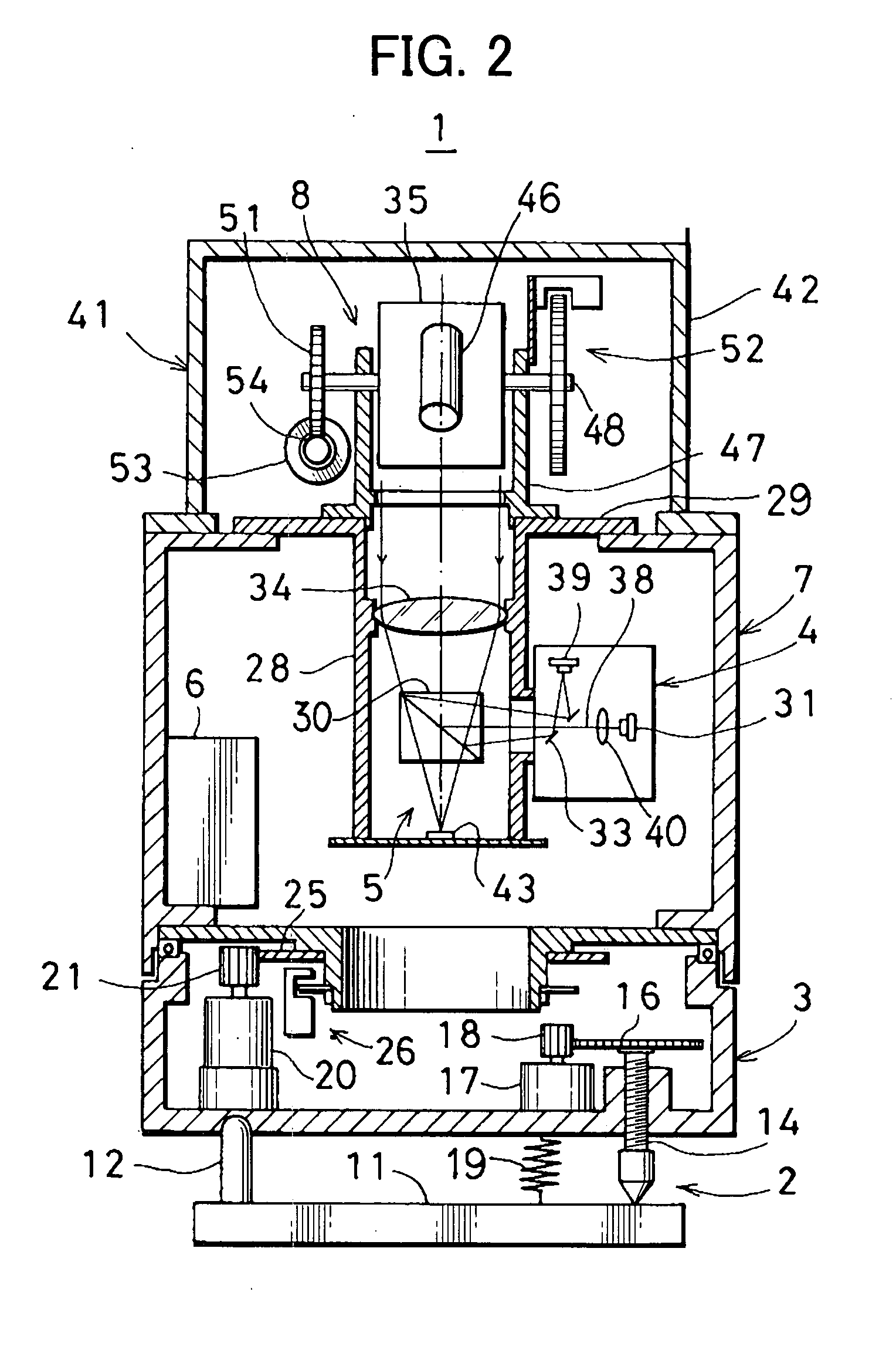
[0025]FIG. 1 and FIG. 2 each represents a position measuring system in the invention.

[0026]A laser scanner 1 comprises a leveling unit 2, a rotary mechanism 3 installed on the leveling unit 2, a measuring system main unit 7 supported by the rotary mechanism 3 and including a distance measuring unit 4, an image pickup unit 5, a control unit 6, etc., and a rotary projection unit 8 installed on an upper portion of the measuring system main unit 7. For convenience purpose, FIG. 2 shows only a condition when the rotary projection unit 8 is seen from a lateral direction with respect to FIG. 1.

[0027]Now, description will be given on the leveling unit 2.

[0028]A pin 12 is erected on a base unit 11. The upper end of the pin 12 is formed with a curved surface and is tiltably engaged in a concave portion on the bottom surface of a lower casing 13. At other two points on the bottom surface, adjusting screws 14 are screwed in and are penetrating through. On the lower end of each of the adjusting ...

second embodiment

[0085]FIG. 9 shows a position measuring system in the invention.

[0086]In FIG. 9, the components shown in FIG. 1, FIG. 2 and FIG. 3 are referred by the same symbols, and the details are not shown.

[0087]In the second embodiment, the measuring direction observing means is provided separately from the elevation rotary mirror 35.

[0088]On an upper surface of the main unit casing 27, a sighting device 84, serving as the measuring direction observing means, is provided, and an upper casing 41 is arranged on the main unit casing 27 via the sighting device 84.

[0089]Inside the upper casing 41, the elevation rotary mirror 35 is rotatably supported around a horizontal rotation shaft (perpendicular to the paper surface), and is rotated by an actuator as required. The rotation angle is detected by the elevation angle detector as an elevation angle. Supporting mechanism, driving mechanism, etc. of the elevation rotary mirror 35 are similar to those explained in connection with the first embodiment,...


PUM


Abstract

A laser scanner, comprising a mirror rotatably provided, a driving unit for rotating the mirror, a distance measuring unit for projecting a distance measuring light for scanning to a measurement range via the mirror and for obtaining a position data by receiving the reflected distance measuring light via the mirror, a measuring direction observing means for indicating a projecting direction of the distance measuring light, and an operation unit for setting the measurement range by designating at least two measuring directions based on the result of observation of the measuring direction obtained by the measuring direction observing means.

Description

BACKGROUND OF THE INVENTION[0001]The present invention relates to a laser scanner for acquiring three-dimensional data of an object to be measured by projecting a distance measuring light to the object to be measured, by measuring a distance to the object to be measured after receiving a light reflected from the object, and by detecting a projecting direction of the distance measuring light when measurement is made.[0002]A type of laser scanner is known, by which it is possible to perform measurement at a multiple of points on an object to be measured. The laser scanner projects a pulsed laser beam as a distance measuring light and scans over a measurement area as required including an object to be measured and measures a distance by receiving a light reflected from the object to be measured for each pulsed laser beam, and acquires three-dimensional data by detecting a direction (i.e. horizontal angle and elevation angle) of the pulsed laser beam at the time of distance measurement....

Claims


Application Information

Patent Timeline
Patent Type & Authority Applications(United States)
IPC IPC(8): G01C3/08
CPCG01C15/002G01S17/42G01S7/4817
Inventor KUMAGAI, KAORUYOSHINO, KEN-ICHIROTANAKA, YASUSHI
Owner KK TOPCON
Why Eureka
Try Eureka