Perpendicular magnetic recording medium, manufacturing method thereof and magnetic recording device

a technology of magnetic recording medium and manufacturing method, which is applied in the direction of recording information storage, erasing method, instruments, etc., can solve the problems of difficult reproduction, and achieve the effect of easy thermal relaxation and the like of reproduction signals

Active Publication Date: 2008-03-27
RESONAC CORP
View PDF21 Cites 10 Cited by
  • Summary
  • Abstract
  • Description
  • Claims
  • Application Information

AI Technical Summary

Benefits of technology

[0016]Here, the description will be given of the reason that the AC erase process is adopted in the perpendicular magnetic recording. FIG. 36 shows a reproduction signal in the case where a signal of a constant frequency is recorded in a perpendicular magnetic recording medium in which a single piece of DC erased portion to which the DC erase process was performed is arranged between two pieces of AC erased portions to which the AC erase process was performed. When the signal is recorded in the DC erased portion, the influence of demagnetizing field is large, and the offset of the signal is easily caused, as shown in FIG. 36. Therefore, asymmetry of the signal (reproduction signal) detected by the magnetic head increases, and a recording / reproducing characteristic degrades. Meanwhile, in the DC erased portion, since it is placed in the same state as the state where the magnetic field is applied always in the same direction backed by the demagnetizing field, inverse magnetic field possibly arises as time goes on or a part of the magnetization is possibly reversed (thermally relaxed). Meanwhile, no offset is caused in the AC erased portion, in which no inverse domain and thermal relaxation possibly arise. Based on the reason as described above, as an initialization process, the AC erase process is adopted in the perpendicular magnetic recording. However, as previously described, when the AC erase process is performed to the discrete track medium, an appropriate reproduction becomes difficult.
[0018]However, according to the verification performed by the present inventor, after the AC erase process was performed to the discrete track medium, as shown in FIG. 37, signal output constantly indicates a zero level, and no preamble portion 62 and pit portion 63 can be detected. In other words, the servo pattern cannot be detected, and no trucking is allowed. Also, after the DC erase process was performed, as shown in FIG. 37, it is possible to detect the preamble portions 62 and the pit portions 63, however, asymmetry, thermal relaxation and the like of the reproduction signal is easily caused in the recording track positioning between the discrete portions 61 as described above.

Problems solved by technology

However, as previously described, when the AC erase process is performed to the discrete track medium, an appropriate reproduction becomes difficult.
Here, a problem when the AC erase process is performed to the discrete track medium will be described. FIG. 37 is a view showing a servo pattern and recording tracks sandwiching the servo pattern therebetween.

Method used


Image

  • Perpendicular magnetic recording medium, manufacturing method thereof and magnetic recording device
  • Perpendicular magnetic recording medium, manufacturing method thereof and magnetic recording device
  • Perpendicular magnetic recording medium, manufacturing method thereof and magnetic recording device

Examples


first embodiment

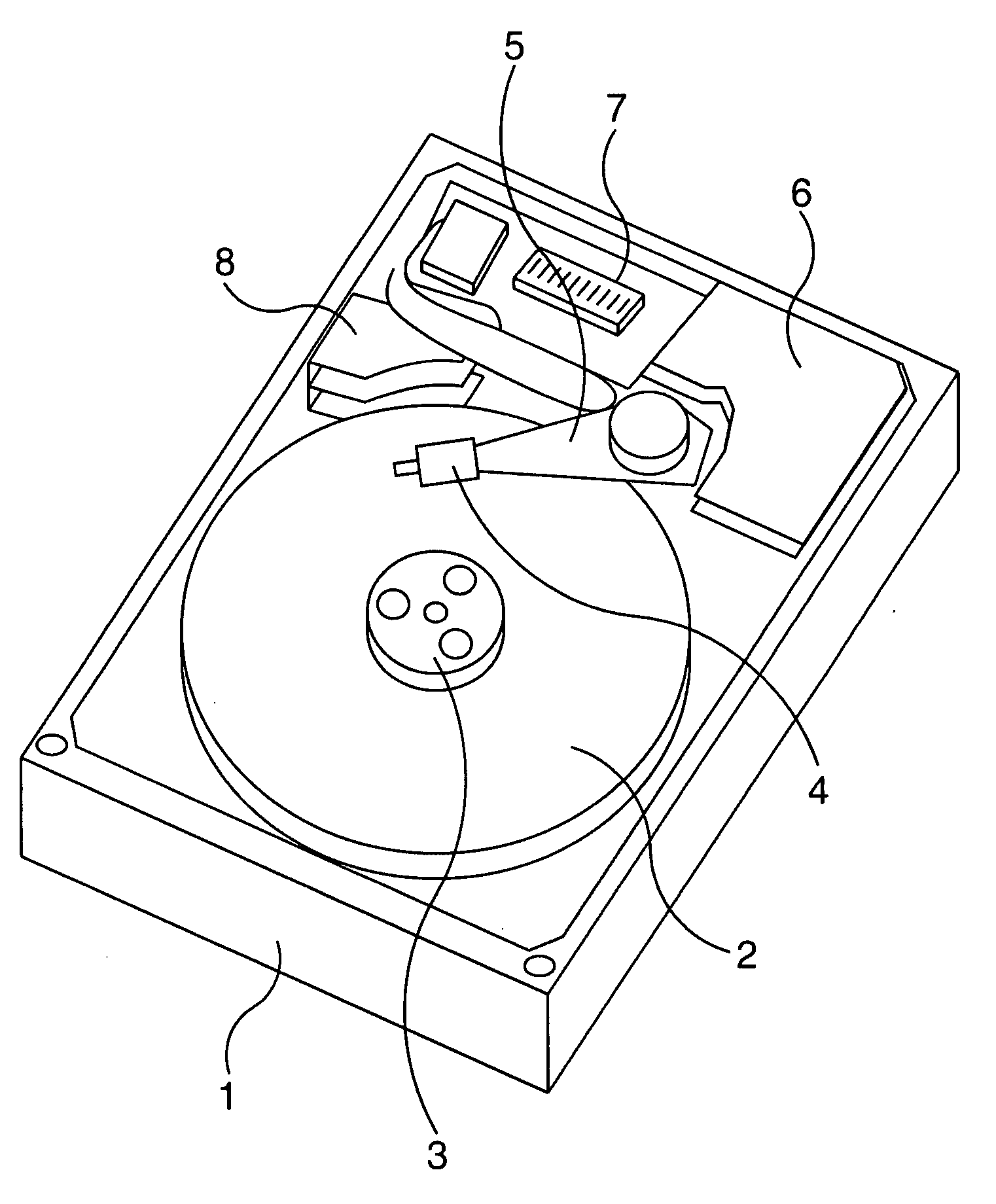
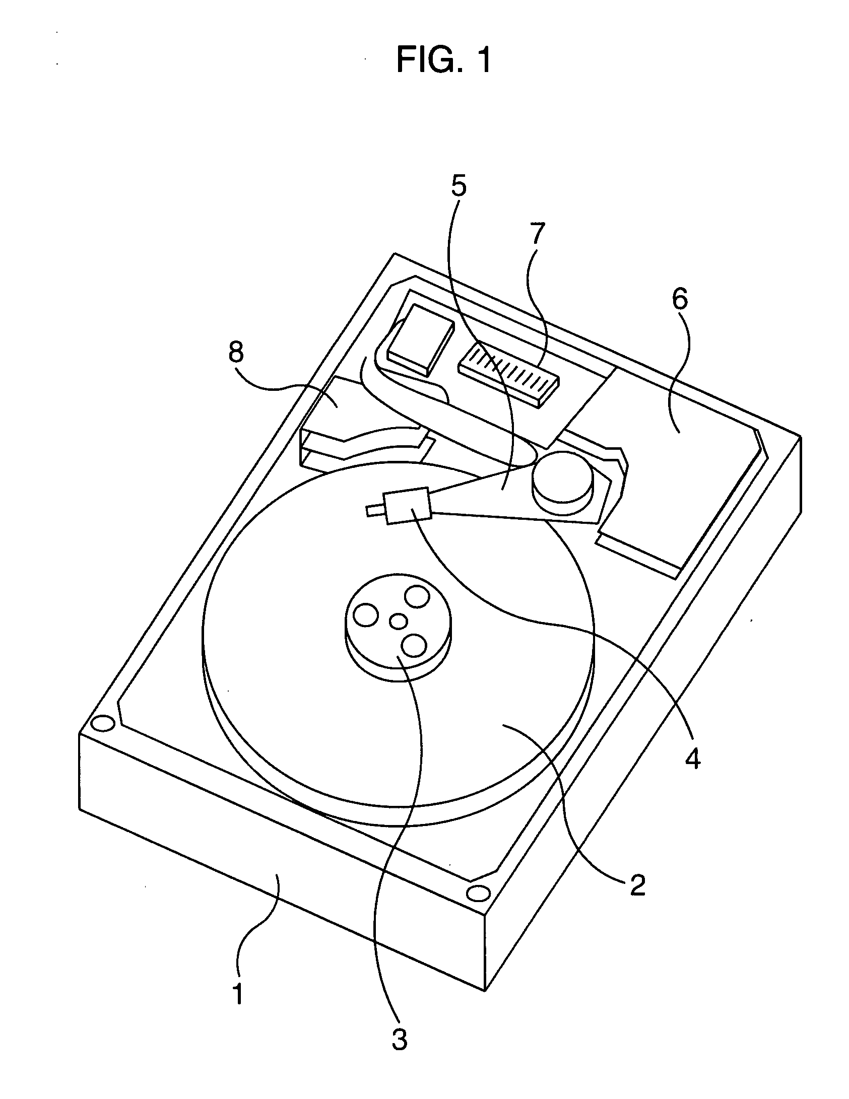
[0061]Firstly, a first embodiment of the present invention will be described. FIG. 1 is a schematic diagram showing a structure of a magnetic recording device (hard disk device) according to the first embodiment of the present invention.

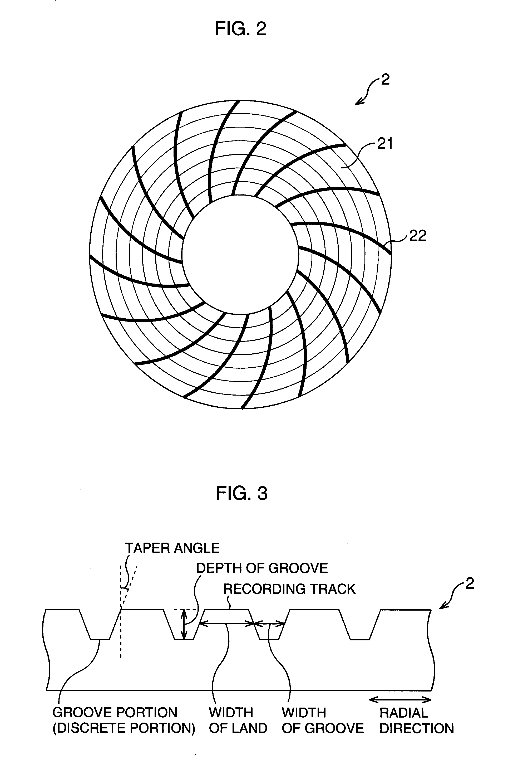
[0062]In the hard disk device, a magnetic recording medium 2, a spindle motor 3, a magnetic head 4, a suspension 5, a voice coil motor 6, a control circuit 7 and a ramp 8 are arranged on a base 1. The hard disk device records / reproduces information into / from the magnetic recording medium 2 using the magnetic head 4 by turning the magnetic recording medium 2 of a disk shape at a predetermined speed by the spindle motor 3. When the hard disk device is in operation, the magnetic head 4 flies about 10 nm above the surface of the magnetic recording medium 2 and the flying amount is kept by the suspension 5. Further, as shown in FIG. 2, the magnetic recording medium 2 includes a plurality of recording tracks 21 provided circumferentially, and a servo patte...

second embodiment

[0080]Subsequently, a second embodiment of the present invention will be described. In the first embodiment, with the use of the servo pattern 22 including the preamble portions 32 and the pit portions 33, the tracking to the desired track is realized. However, as shown in FIG. 12, when a micro defect 34 or the like exists in the vicinity of the preamble portions 32 and / or the pit portions 33, correct signal detection is impossible, and correct tracking becomes difficult. The reason thereof is as described below. Specifically, the signal recorded in the recording track 21 as user information and the like is detected as a peak to peak value in the positive and negative direction in accordance with the magnetization direction, while the signal of the servo pattern 22 is detected as a zero to peak value. Therefore, the detected signal from the servo pattern 22 is a half of the detected signal from the recording track 21 even when modulation amplitude thereof is at maximum. In other wor...

third embodiment

[0089]Subsequently, a third embodiment of the present invention will be described. FIG. 15 is a schematic diagram showing the magnetic recording medium 2 in the third embodiment of the present invention.

[0090]In the second embodiment, the servo pattern 22 is provided in the DC erased portion 42, however, in the third embodiment, by performing the AC erase process also to the DC erased portion 42, the circumference of the servo pattern 23 is made to be an AC erased portion 43.

[0091]According to the third embodiment as described above, since the signal is not detected from the servo pattern 22 as shown in FIG. 15, the tracking control at the time of the actual operation is inevitably performed based on the servo pattern 23. Therefore, as shown in FIG. 16, even if the servo pattern 22 has the micro defect 34 such as a foreign matter attached or the like, the correct control excluding thermal asperity arising together with the micro defect 34 can be performed. In other words, when the f...


PUM

PropertyMeasurementUnit
widthaaaaaaaaaa
taper angleaaaaaaaaaa
widthaaaaaaaaaa

Abstract

A servo pattern is positioned in a DC erased portion to which a DC erase process has been performed, and recording tracks and track groove portions (discrete portions) are positioned in an AC erased portion to which an AC erase process has been performed. The track groove portions extend in a circumferential direction. The AC erased portion and the DC erased portion are both made of a magnetic material. In the servo pattern, four lines of preamble portions extending almost in a radial direction are formed and a plurality of pit portions disposed in a dotted manner in two lines are arranged. The pit portions are positioned rearward of the preamble portions in respect of a scanning direction of a magnetic head.

Description

CROSS-REFERENCE TO RELATED APPLICATIONS[0001]This application is based upon and claims the benefit of priority from the prior Japanese Patent Application No. 2006-256343, filed on Sep. 21, 2006, the entire contents of which are incorporated herein by reference.BACKGROUND OF THE INVENTION[0002]1. Field of the Invention[0003]The present invention relates to a perpendicular magnetic recording medium suitable to increase recording density, a manufacturing method thereof and a magnetic recording device.[0004]2. Description of the Related Art[0005]In a hard disk device being one of recording devices, recording density is on the logarithmic increase. In an aim of increasing recording density, studies on the perpendicular magnetic recording, which magnetizes in the perpendicular direction to the surface of a magnetic recording medium, show progresses, while a longitudinal recording, which magnetizes in the parallel direction with the surface of the magnetic recording medium, has been employ...

Claims


Application Information

Patent Timeline
Patent Type & Authority Applications(United States)
IPC IPC(8): G11B5/127
CPCG11B5/024G11B5/1278G11B5/855G11B5/59688G11B5/59655
Inventor AOYAMA, NOBUHIDE
Owner RESONAC CORP
Why Eureka
Try Eureka