Connector assembly, receptacle type connector, and interface apparatus

a technology of connectors and connector assemblies, applied in the direction of securing/insulating coupling contact members, coupling device connections, electric discharge lamps, etc., can solve the problems of insufficient reduction of hifix costs, huge manpower and skilled workers, and increase the cost of hifix, so as to reduce the number of parts , the effect of reducing ground loop interferen

Inactive Publication Date: 2008-03-27
ADVANTEST CORP +1
View PDF10 Cites 29 Cited by
  • Summary
  • Abstract
  • Description
  • Claims
  • Application Information

AI Technical Summary

Benefits of technology

[0022]In the receptacle of the present invention, the first signal contact and the second signal contacts preferably have the same shapes. The three contacts of the single-wire plug preferably are the same in shape as each other to reduce the number of parts. Therefore, preferably the first signal contact and the second signal contacts to be connected to are also the same in shape as each other.
[0023]Here, the first signal contact and the pair of ground contacts forming the first group of contacts have to be electrically isolated from each other. The first signal contact and the pair of second signal contacts forming the second group of contacts also have to be electrically isolated from each other. However, the ground contacts of the first group of contacts and the second signal contacts of the second group of contacts may be electrically connected with each other. Therefore, in the receptacle of the present invention, the ground contacts and the second signal contacts positioned at the same side of the first signal contact are preferably formed integrally. Compared with making the members independent from each other, the number of parts can be reduced, so the contact unit can be configured at a high density. Due to this configuration, as explained later, the ground loop interference can be reduced. Further, by configured in this way, it is possible to reduce the number of external connection contacts for four contacts to two. Combined with the one external connection contact by sharing the above-mentioned signal contact, a total of three external connection contacts become sufficient.
[0024]The present invention can make a receptacle comprising a plurality of contact units consisting of the first group of contacts and the second group of contacts. In this case, the contact units are preferably arranged in a zigzag configuration. In the same way as a differential transmission connector, the ground contacts and the signal contacts are alternately arranged. As a result, a drop in the high frequency characteristics can be avoided.

Problems solved by technology

This consumes tremendous manpower and requires skilled workers and therefore has become a factor behind higher costs in a HiFix.
For that reason, it is necessary to prepare a plurality of types of connectors corresponding to all of the cables and therefore the costs of HiFix have not been able to be sufficiently reduced.

Method used


Image

  • Connector assembly, receptacle type connector, and interface apparatus
  • Connector assembly, receptacle type connector, and interface apparatus
  • Connector assembly, receptacle type connector, and interface apparatus

Examples


first embodiment

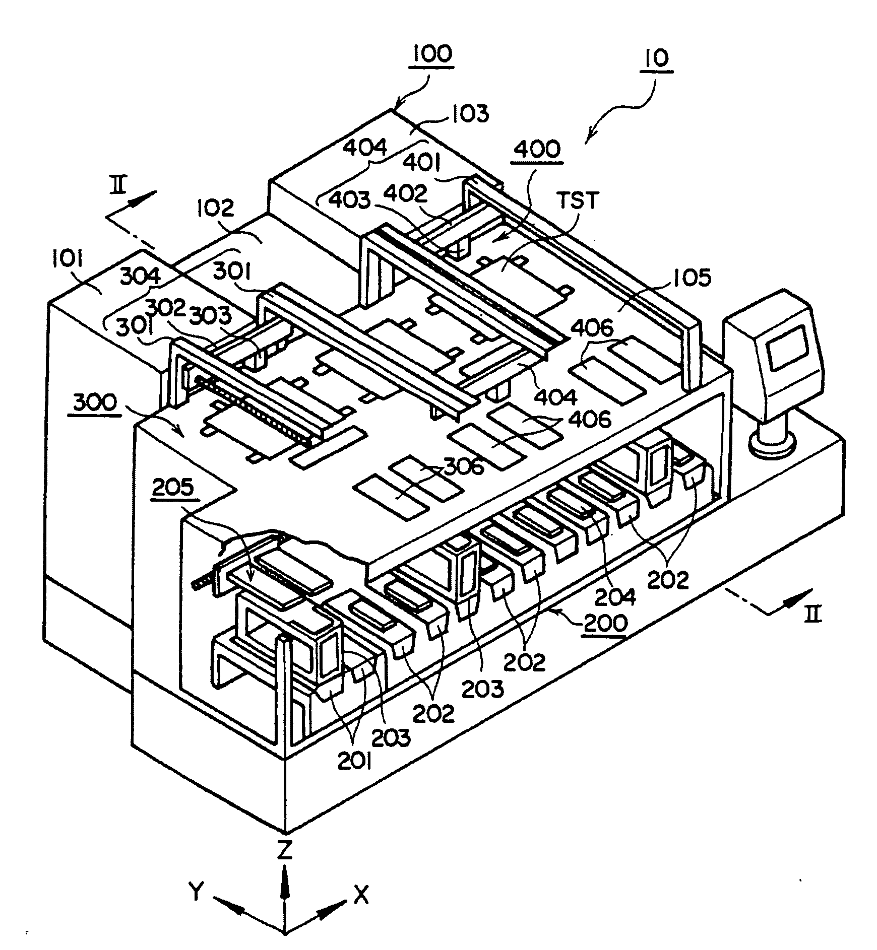
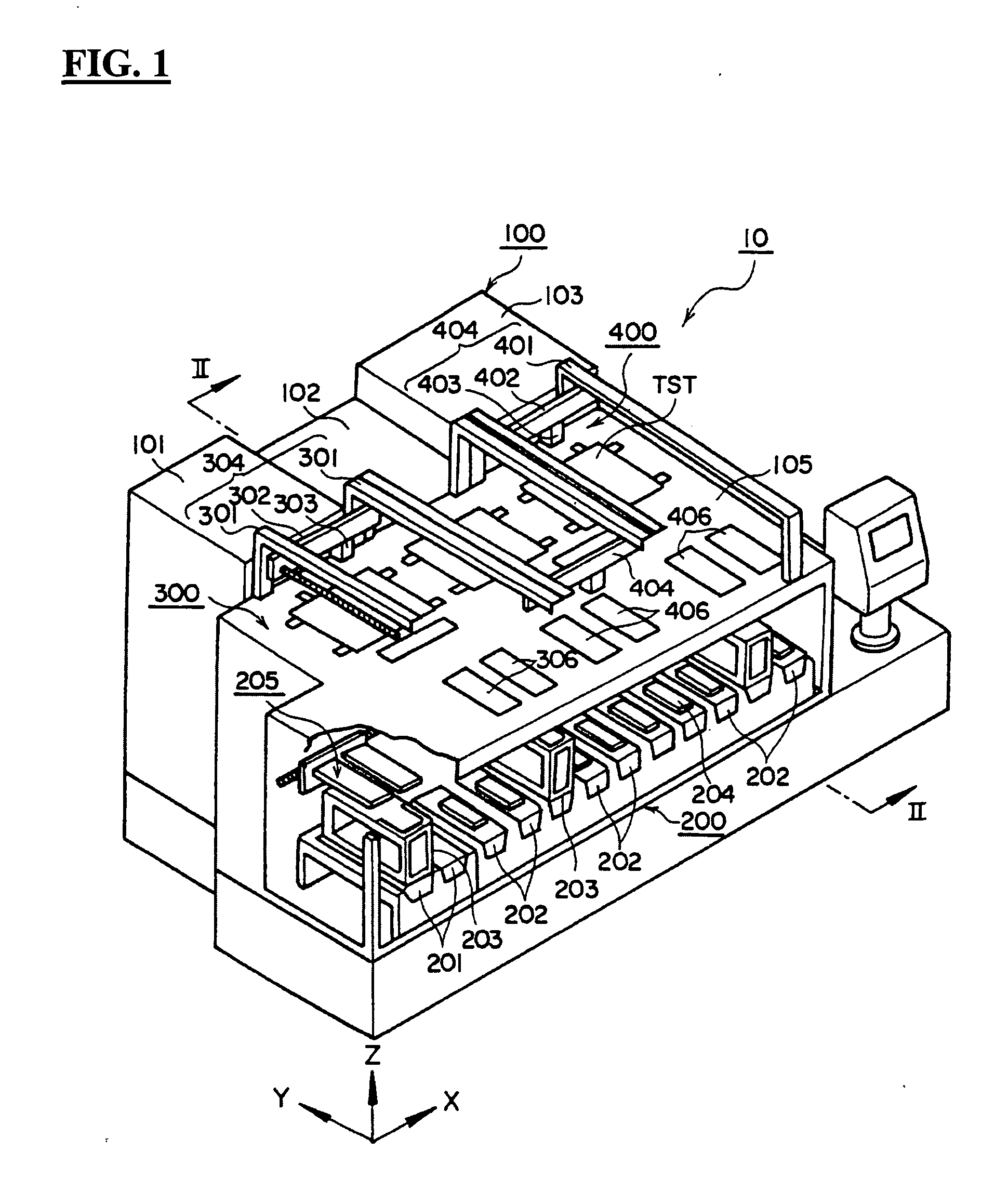
[0055]FIG. 1 is a perspective view showing an entire electronic device test apparatus according to the present embodiment, FIG. 2 is a schematic sectional view along the line II-II of FIG. 1, and FIG. 3 is a back view of the electronic device test apparatus shown in FIG. 1. First, the overall configuration of an electronic device test apparatus according to the present embodiment will be explained in brief with reference to FIG. 1 to FIG. 3.

[0056]The electronic device test apparatus 1 according to the present embodiment, as shown in FIG. 1 and FIG. 2, comprises a handler 10 for handling IC devices under test, a test head 4 to which IC devices under test are electrically connected, and a tester 3 for sending test signals to this test head 4 to run tests on the IC devices under test.

[0057]The handler 10 is a apparatus for supplying IC devices to the test head 4 in the state with the IC devices under test given high temperature or low temperature thermal stress and classifying the IC d...

second embodiment

[0146]FIG. 19 is a cross-sectional view showing a HiFix and a test head according to a second embodiment of the present invention.

[0147]The HiFix 5B according to the present embodiment, as shown in FIG. 19, is a CLS (Cable Less) type of HiFix enabling a change in kind of IC devices under test to be handled by replacement of a topmost DSA (Device Specific Adapter) 90. This HiFix 5B, as shown in the drawing, comprises a mother board 51 mounted on the top of the test head 4 and a DSA 90 mounted to this mother board 51.

[0148]The HiFix 5B according to the present embodiment is configured integrally from the sockets 99 to the spacing frame 93 as the DSA 90. This differs from the HiFix 5A according to the first embodiment in the point that the DSA 90 can be attached to and detached from the mother board 51 by the connectors 92.

[0149]The DSA 90 is configured with the spacing frame 93 provided on top of performance boards 91 and further with socket boards 98 provided on top of them through s...

third embodiment

[0153]FIG. 20 is a cross-sectional view showing a HiFix and a test head according to a third embodiment of the present invention.

[0154]The HiFix 5C according to the present embodiment, as shown in FIG. 20, is a CCN (Cable Connection) type of a HiFix where the entire HiFix 5C is replaced each time changing the kind of the IC devices under test. This HiFix 5C differs from the HiFixes 5A, 5B according to the first embodiment and second embodiment in the point that there are no separable locations at the HiFix SC at all.

[0155]At the bottommost part of this HiFix 5C, a plurality of intermediate connectors 6 explained in the first embodiment are provided in the state arranged substantially in parallel along the depth direction of the HiFix SC. The device side connectors 8 attached to the ends of the electrical cables 7 are detachably connected to the engagement holes 601 of the intermediate connectors 6.

[0156]The other ends of the electrical cables 7 are directly connected by soldering to...


PUM


Abstract

A connector assembly, for electrically connecting electrical cables 7 to a test head 4, comprises a plurality of types of cable side connectors 8 respectively attached to one end of the electrical cable 7; and a intermediate connector 6 to which the plurality of types of cable side connectors 8 are connected in a detachable manner, and the intermediate connector 6 having a first engagement part 501 having a shape with which all types of cable side connectors 8 can be engaged and an output terminal 602 able to be engaged with a test head side connector 41 electrically connected to a pin electronics board of the test head 4.

Description

TECHNICAL FIELD[0001]The present invention relates to a connector assembly for electrically connecting an electrical cable to a circuit board, a receptacle type connector forming part of that connector assembly, and an interface apparatus for interconnecting electrical connections between a test head and devices under test in an electronic device test apparatus.BACKGROUND ART[0002]In the process of production of semiconductor integrated circuit devices and other various electronic devices (hereinafter also referred to as “IC devices”) , an electronic device test apparatus is used for testing performances and functions of IC devices in the state formed on a wafer or in a packaged state.[0003]This electronic device test apparatus uses a handler or prober to electrically connect IC devices to a test head and uses a tester to run tests on them. The test head is provided on top with an interface apparatus for interconnecting electrical connections between the IC devices and the test head...

Claims


Application Information

Patent Timeline
Patent Type & Authority Applications(United States)
IPC IPC(8): H01R9/05
CPCH01R31/06H01R13/42
Inventor MATSUMURA, SHIGERUOSAWA, KAZUTAKAHAMA, HIROYUKIIZUMI, YUICHIROTAKEMASA, EIICHIRO
Owner ADVANTEST CORP
Why Eureka
Try Eureka